Conózcanos
Recuperación de calor residual y equipos químicos
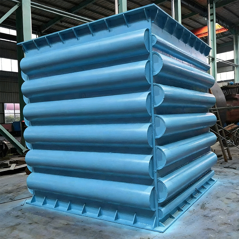
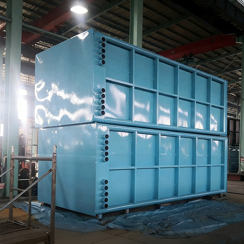
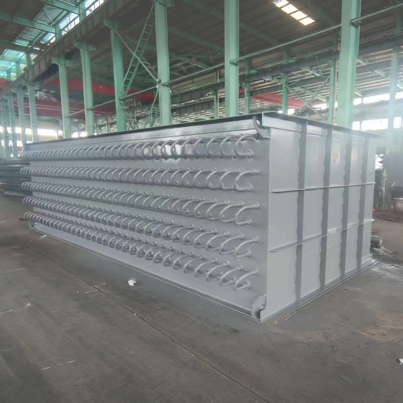
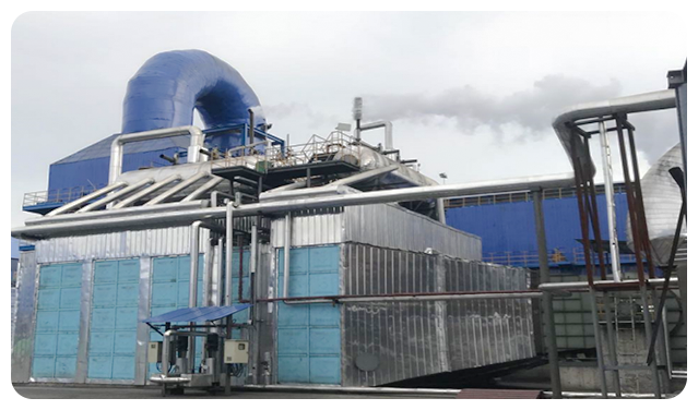
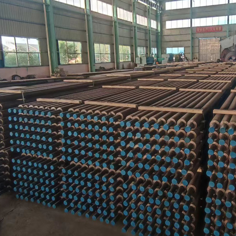
Fundada en 2005, la empresa se especializa en la investigación y el desarrollo y la fabricación de sistemas de recuperación de calor y equipos químicos para desechos de gases de combustión, y posee capacidades internas integrales que abarcan desde el desarrollo de tubos de calor y soldadura fuerte a base de níquel hasta la fabricación de recipientes a presión. Nuestros productos se utilizan ampliamente en las industrias química del carbón, metalúrgica, de generación de energía y de amoníaco sintético, y se han exportado a mercados extranjeros.
Jiangsu Shineng Chemical Equipment Co., Ltd.
Jiangsu Shineng Chemical Equipment Co., Ltd. Jiangsu Shineng Chemical Equipment Co., Ltd. Jiangsu Shineng Chemical Equipment Co., Ltd.
  • Jiangsu Shineng Chemical Equipment Co., Ltd.
    Garantía de calidad

    Certificada para recipientes a presión ASME y Clase III, con sistemas completos de gestión ISO. Equipos avanzados y técnicos cualificados garantizan un estricto control de calidad durante todo el proceso de fabricación.

  • Jiangsu Shineng Chemical Equipment Co., Ltd.
    Innovación en diseño

    Cuenta con un Instituto de Investigación de Tuberías de Calor dedicado y asociaciones universitarias. Posee casi 100 patentes, incluida tecnología de soldadura fuerte con níquel para tubos con aletas de 16 metros.

  • Jiangsu Shineng Chemical Equipment Co., Ltd.
    Influencia de la industria

    Proveedor designado para normas nacionales de ingeniería química. Los productos sirven a las principales industrias en China e internacionalmente, obteniendo un amplio reconocimiento en el mercado.

Amplia cobertura de industrias
Industrias a las que servimos
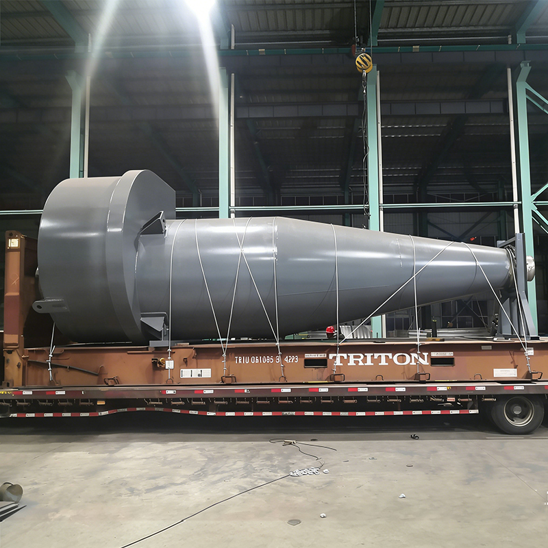
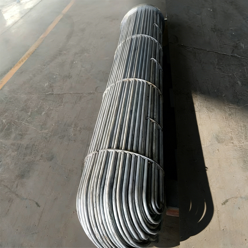
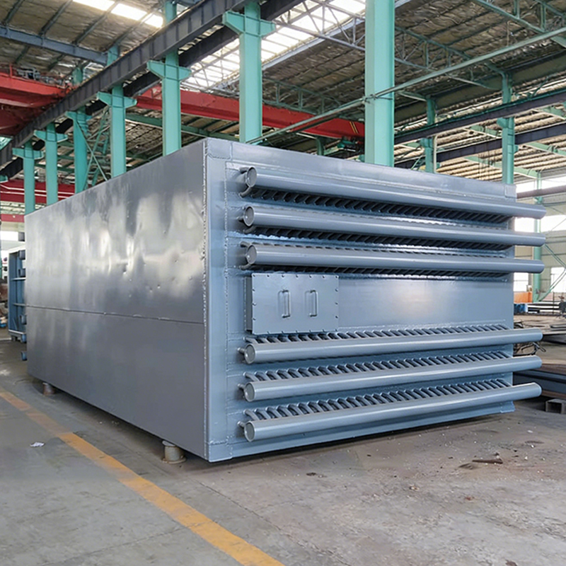
Proporcionamos equipos básicos como economizadores de tubos de calor, calderas de calor residual, precalentadores de aire, colectores de polvo ciclónico, varios intercambiadores de calor y torres para industrias como la química del carbón, la energía, la metalurgia y el amoníaco sintético. También podemos emprender el diseño, fabricación y puesta en marcha de proyectos de recuperación de calor residual a nivel de sistema.
  • Jiangsu Shineng Chemical Equipment Co., Ltd.
  • Jiangsu Shineng Chemical Equipment Co., Ltd.
  • Jiangsu Shineng Chemical Equipment Co., Ltd.
  • Jiangsu Shineng Chemical Equipment Co., Ltd.
Jiangsu Shineng Chemical Equipment Co., Ltd.
Categorías de productos
Nuestros productos populares

Jiangsu Shineng Chemical Equipment Co., Ltd. es un conocido fabricante profesional de equipos de intercambio de calor de tubos de calor de alta eficiencia, conjuntos completos de equipos de calderas de calor residual y equipos de recipientes a presión en China.

Jiangsu Shineng Chemical Equipment Co., Ltd.
Noticias y blogs
Más noticias de nuestra industria

Nos mantenemos actualizados con las últimas novedades de la empresa y la industria. Contáctenos y siga nuestra información sobre exposiciones.

Jiangsu Shineng Chemical Equipment Co., Ltd.
  • Jiangsu Shineng Chemical Equipment Co., Ltd.

    La purga de calderas es una eliminación controlada del agua concentrada de la caldera del tambor de vapor o de los cabezales inferiores para mantener los sólidos suspendidos y disueltos dentro de límites seguros. No es señal de mal funcionamiento; Es una parte necesaria de la gestión química del agua de calderas industriales. Un plan de purga eficaz protege las superficies de transferencia de calor, mejora la calidad del vapor y reduce los costos de mantenimiento. Para los ingenieros de plantas y los equipos de adquisiciones, el desafío es equilibrar el control de la química del agua con la eficiencia energética. Esta guía explica los fundamentos de la purga de calderas, los procedimientos operativos seguros, las opciones de recuperación de calor y los criterios para elegir equipos y proveedores confiables.

    ¿Qué es la purga en una caldera?

    La purga es la descarga deliberada de una porción del agua de la caldera y su reemplazo con agua de alimentación que tiene un menor contenido de sólidos disueltos. El agua de alimentación de cada caldera aporta impurezas como calcio, magnesio, sílice, cloruro y alcalinidad. Cuando el agua de alimentación se convierte en vapor, esas impurezas permanecen y se acumulan en el agua de la caldera. A medida que aumentan los sólidos disueltos totales (TDS), el agua se vuelve más conductora, tiende a formar espuma y puede liberar gotas que contienen sólidos disueltos con el vapor. Ese problema se conoce como arrastre. Las incrustaciones comienzan a depositarse en las superficies de los tubos y tambores cuando el calcio y el magnesio exceden sus límites de solubilidad. Por lo tanto, el propósito de la purga de la caldera es mantener el TDS y los sólidos suspendidos por debajo del umbral donde pueden ocurrir incrustaciones, corrosión o arrastre. La purga puede ser manual o automática, intermitente o continua, según el tipo de caldera y la estrategia de tratamiento del agua.

    La purga es una herramienta química del agua, no un flujo de desechos que deba ignorarse: la tasa correcta mantiene la caldera limpia sin quemar el exceso de combustible.

    Por qué es importante la purga: eficiencia, seguridad y química del agua

    La formación de incrustaciones en los tubos de las calderas es la consecuencia más común de una purga insuficiente. Incluso una fina capa de incrustaciones actúa como aislante, ralentizando la transferencia de calor y provocando que aumente la temperatura del metal de los tubos. Con el tiempo, esto provoca sobrecalentamiento, fallas en los tubos y reparaciones costosas. El arrastre tiene un efecto igualmente grave sobre la calidad del vapor. El vapor que contiene agua de caldera transporta sales disueltas que pueden depositarse en las palas de las turbinas, las superficies del intercambiador de calor y los equipos de proceso. La corrosión, a menudo por debajo de las incrustaciones, debilita aún más las piezas de presión. La purga en sí misma puede parecer una pequeña pérdida de agua, pero en términos energéticos, cada descarga envía agua saturada fuera de la caldera. El desafío es eliminar suficientes sólidos para mantener limpia la caldera sin desperdiciar calor excesivo. Por lo tanto, los operadores de plantas deben medir el TDS o la conductividad con una frecuencia definida y establecer un rango objetivo basado en la presión de la caldera y las recomendaciones del fabricante.

    Las tasas de purga influyen directamente en la eficiencia general de la caldera porque el agua caliente que sale de la caldera debe compensarse calentando el agua de alimentación fría. En muchas plantas industriales, la tasa de purga no se mide, por lo que las pérdidas de energía quedan ocultas dentro del funcionamiento rutinario. Una comparación visual ayuda a los equipos de planta a comprender la magnitud de esta pérdida en función de las tasas de purga comunes. Las barras horizontales a continuación muestran las pérdidas típicas de energía del combustible para tasas de purga del 1%, 2%, 5% y 10% a una presión operativa de alrededor de 10 a 15 bar. Los valores son aproximados y dependen de la temperatura del agua de alimentación, la presión de la caldera y el equipo de recuperación de calor.

    1% BD
    0,5%
    2% BD
    1,0%
    5% BD
    2,5%
    10% BD
    5,0%

    El gráfico muestra que una tasa de purga del 1% crea una penalización de combustible relativamente pequeña, aunque aún puede valer la pena recuperarla. Al 2%, una planta comienza a sentir el coste en las facturas de combustible si la caldera funciona de forma continua. Con un 5%, la pérdida de energía se convierte en un gasto operativo importante, especialmente para calderas de más de 10 t/h. Al 10%, la pérdida de combustible puede ser del 3 al 5% o más, lo que a menudo indica un tratamiento deficiente del agua de alimentación o un control defectuoso. Reducir la tasa de purga del 10% al 2%, por ejemplo, puede mejorar la eficiencia de la caldera en aproximadamente un 3%. Para una caldera de 20 t/h que funciona 8.000 horas al año, esto puede ahorrar cientos de megavatios-hora equivalentes en combustible. El mejor enfoque es tomar muestras del agua de la caldera con regularidad y ajustar la purga para mantener el TDS objetivo. Muchos operadores usan una regla simple: purgar sólo lo necesario para mantener el TDS por debajo del límite especificado para la presión de la caldera. La recuperación de calor puede reducir el costo de la inevitable purga. Si se envía una corriente de purga continua a través de un intercambiador de calor, la mayor parte de la entalpía puede regresar al sistema. Es por eso que las plantas modernas tratan la purga no como un desperdicio sino como un recurso recuperable.

    La tasa de purga óptima es la tasa mínima que mantiene la química del agua de la caldera dentro de límites seguros.

    Tipos de purga de calderas

    La purga de calderas generalmente se divide en dos métodos principales: purga de fondo y purga de superficie. Se dirigen a diferentes tipos de contaminación y operan en diferentes horarios. La purga de fondo extrae lodos y sedimentos que se depositan en las partes más bajas de la caldera. La purga de superficie elimina los sólidos disueltos y la espuma que se concentran cerca de la línea de flotación. La siguiente tabla resume las principales diferencias.

    Comparación entre purga de fondo y purga de superficie.
    Parámetro Purga de fondo Purga de superficie
    Objetivo principal Lodos, sedimentos, sólidos en suspensión Sólidos disueltos, espuma, espuma.
    Ubicación Parte inferior del tambor de lodo y cabezales. Cerca de la línea de flotación en el tambor de vapor.
    Método de funcionamiento Ráfagas cortas e intermitentes Skimmer continuo o intermitente
    Descarga de válvula Alto flujo, baja duración Flujo bajo, duración alta
    Idoneidad de la recuperación de calor Menos adecuado debido al flujo intermitente Muy adecuado para la recuperación continua de calor.

    Purga continua versus intermitente

    La purga de superficie a menudo se opera continuamente para mantener un nivel estable de TDS. Se extrae un pequeño chorro de agua del tambor de vapor y se reemplaza por agua de alimentación. Los controladores automáticos miden la conductividad y modulan una válvula para alcanzar el punto de ajuste objetivo. La purga intermitente, por el contrario, es una operación manual periódica. Es más eficaz para eliminar los lodos de las partes más bajas de la caldera. Generalmente se prefiere la purga continua para controlar los sólidos disueltos, mientras que la purga intermitente del fondo sigue siendo necesaria para la eliminación de sedimentos.

    Utilice una purga continua de la superficie para controlar la concentración de productos químicos y una purga periódica del fondo para eliminar los lodos.

    Componentes del sistema de purga y procedimiento de operación segura

    Una línea de purga bien diseñada generalmente incluye una válvula de apertura lenta, una válvula de apertura rápida, una disposición en T y un tanque de purga o recipiente de enfriamiento. La válvula de apertura lenta generalmente se instala más cerca de la caldera y se usa para estrangular el flujo la primera vez. La válvula de apertura rápida se coloca aguas abajo y actúa como control todo/nada. Se agregan enfriadores de muestreo y sondas de conductividad para el monitoreo de la calidad del agua. Los sistemas automáticos reemplazan la válvula manual de apertura rápida por una válvula moduladora motorizada o accionada por aire.

    • Válvula de apertura lenta: protege la válvula exterior de una erosión severa.
    • Válvula de apertura rápida o de bola: proporciona un rápido aislamiento de encendido/apagado.
    • Tanque de purga o recipiente de flasheo: enfría la descarga y separa el vapor flash.
    • Enfriador de muestras: reduce la temperatura de forma segura para una medición precisa de TDS.
    • Sonda y controlador de conductividad: permite una purga automática continua.

    La purga manual segura sigue una secuencia estricta. La secuencia exacta puede variar según la disposición de la válvula, pero el principio fundamental es evitar presurizar o calentar una sección cerrada de la tubería.

    1. Confirme que la presión de la caldera esté dentro del rango normal y que el tanque de purga esté listo.
    2. Notifique al personal operativo y aísle cualquier equipo posterior que pueda resultar dañado.
    3. Abra primero la válvula de apertura lenta más cercana a la presión de la caldera.
    4. Abra lentamente la válvula de apertura rápida durante un breve período de descarga.
    5. Cierre la válvula de apertura rápida, deje que la caldera se estabilice y repita según sea necesario.
    6. Después del recorrido final, cierre primero la válvula de apertura rápida y luego la válvula de apertura lenta.
    7. Verifique las tuberías aguas abajo en busca de fugas o signos de soportes sobrecalentados.

    Los operadores deben mantenerse alejados de la línea de descarga y usar equipo de protección personal completo. El agua caliente y el vapor flash se liberan a gran velocidad y pueden provocar quemaduras graves. Nunca deje una caldera funcionando sin supervisión. Si la tubería vibra o las válvulas tienen fugas, detenga la operación e inspeccione el sistema antes de continuar. En instalaciones que requieren operación remota o automática, se deben aplicar los mismos interbloqueos de seguridad a las válvulas motorizadas.

    Aísle siempre el lado de presión de la caldera antes de ventilar y nunca asuma que una válvula está apretada sin verificar la línea de drenaje.

    Recuperación de calor de la purga de calderas

    Las corrientes de purga salen de la caldera a temperatura de saturación. En una caldera de 10 bar, la temperatura ronda los 180°C; en una caldera de 40 bar, puede superar los 250°C. Descargar esta agua caliente directamente al desagüe desperdicia una gran cantidad de energía térmica. Un tanque de flasheo primero reduce la presión y convierte parte del agua caliente en vapor de baja presión, que puede usarse en el desaireador o para calentar espacios. El líquido caliente restante todavía contiene calor. Un intercambiador de calor puede transferir este calor residual al agua de reposición, al agua de alimentación de la caldera o al agua de proceso. Esta simple modernización a menudo se amortiza en menos de dos años, especialmente en sistemas de purga continua.

    Un intercambiador de calor de carcasa y tubos es una opción común para el enfriamiento por purga y la recuperación de calor porque puede soportar alta presión, alta temperatura y choque térmico. También proporciona a la planta flexibilidad para utilizar el calor recuperado en múltiples servicios.

    Shell and Tube Heat Exchanger for High-Pressure Blowdown Cooling Intercambiador de calor de carcasa y tubos para enfriamiento por purga de alta presión Este robusto intercambiador de calor soporta alta presión, temperatura y choque térmico, lo que lo hace ideal para enfriamiento por purga y recuperación de calor. Su diseño flexible se adapta a múltiples servicios de planta. Ver producto →

    La tecnología de economizador soldado a base de níquel es otra forma comprobada de capturar el calor del agua caliente o de las corrientes de gases de combustión donde la resistencia a la corrosión es fundamental. Este tipo de economizador está diseñado para entornos industriales exigentes y puede integrarse con el precalentamiento del agua de alimentación.

    Nickel-based Brazed Economizer for Corrosive Flue Gas Heat Recovery Economizador soldado a base de níquel para recuperación de calor de gases de combustión corrosivos Diseñado para entornos industriales exigentes, este economizador ofrece una fuerte resistencia a la corrosión y una alta eficiencia de transferencia de calor, lo que ayuda a recuperar el calor del agua caliente o de los flujos de gases de combustión. Ver producto →

    Para instalaciones que prefieren una solución integrada, los paquetes de evaporador e intercambiador de calor pueden combinar enfriamiento instantáneo, calentamiento de líquidos y pulido de condensado en una sola unidad de ingeniería. Estos sistemas son útiles cuando la planta de calderas requiere un circuito de recuperación completo en lugar de un solo componente.

    Integrated Evaporator and Heat Exchanger Package for Complete Recovery Loops Paquete integrado de evaporador e intercambiador de calor para circuitos de recuperación completos Este sistema compacto combina refrigeración instantánea, calentamiento de líquidos y pulido de condensado en una unidad de ingeniería, útil para plantas de calderas que requieren un circuito de recuperación completo en lugar de componentes individuales. Ver producto →

    Al planificar un proyecto de recuperación de calor por purga, considere las horas de operación, el caudal de purga y la cantidad de vapor de baja presión que se puede consumir en el sitio. El calor recuperado puede precalentar el agua de reposición, elevar la temperatura del desaireador o alimentar un circuito de agua caliente a baja temperatura. En muchas industrias, esta recuperación de calor se combina con la recuperación de calor de los gases de combustión de la propia caldera para maximizar la eficiencia general de la planta.

    A menudo es posible recuperar entre el 50 y el 80 por ciento del calor en una corriente de purga continua utilizando un tanque flash y un intercambiador de calor.

    Control automático de purga y mejores prácticas

    La purga manual del fondo sigue siendo común para la eliminación de lodos, pero el control continuo de TDS es más preciso. Las sondas de conductividad monitorean la calidad del agua de la caldera y envían señales a una válvula de control modulante. La válvula se abre lo suficiente para mantener el punto de ajuste deseado. Esto reduce la pérdida de agua en comparación con el muestreo manual, evita el arrastre y estabiliza la calidad del vapor. El controlador se puede vincular a un sistema SCADA de la planta para el registro de tendencias y la gestión de alarmas.

    • Tome muestras del agua de alimentación y del agua de la caldera al menos una vez por turno para calderas grandes.
    • Calibre las sondas de conductividad mensualmente para mantener la precisión.
    • Realice un seguimiento del volumen de purga con un medidor de flujo cuando sea posible.
    • Revise los informes de tratamiento de agua y ajuste el punto de ajuste cuando cambie la carga o la calidad del agua de alimentación.
    • Capacite a los operadores sobre la secuencia correcta y la seguridad de las válvulas de purga manual.
    • Registrar el tiempo de purga del fondo; una duración excesiva puede indicar una válvula rota o una técnica deficiente.

    Un programa de purga bien controlado también reduce el consumo de productos químicos. Cuando el TDS se mantiene dentro de una banda estrecha, la dosificación se puede optimizar y los niveles de inhibidores de incrustaciones se vuelven más predecibles. Esto es particularmente importante para las calderas modernas de alta presión, donde incluso pequeños cambios en la química del agua pueden afectar la confiabilidad de la caldera.

    El control de purga automático combinado con la purga del fondo regular proporciona el mejor equilibrio entre la calidad del vapor, la demanda de agua y la eficiencia energética.

    Selección de equipos de purga y un proveedor calificado

    Al modernizar una planta de calderas, el sistema de purga debe elegirse con el mismo cuidado que el quemador o los tambores de vapor. El proveedor debe comprender la química del agua de la caldera, el diseño de recipientes a presión y la selección de materiales. Para los componentes que soportan presión, la certificación ASME y una licencia nacional para recipientes a presión son calificaciones importantes. Un fabricante con experiencia en la construcción de intercambiadores de calor, economizadores y calderas de calor residual puede integrar la recuperación de calor por purga en el sistema térmico general de la unidad. Ejemplos de experiencias de recuperación de calor residual industrial son visibles en aplicaciones de calderas de calor residual metalúrgicas, donde se aplican principios de recuperación de calor similares en diferentes corrientes de gases de combustión y agua caliente.

    Antes de seleccionar un proveedor, solicite estudios de casos, certificaciones de materiales y cronogramas de entrega. Confirme que el tanque de purga o el intercambiador de calor estén construidos de acuerdo con los códigos aplicables y que el sistema de control pueda comunicarse con su plataforma PLC, DCS o SCADA existente. Un proveedor que pueda proporcionar soporte posventa, válvulas de repuesto y núcleos de transferencia de calor de repuesto reduce el riesgo de tiempo de inactividad. Los compradores de proyectos grandes y los compradores OEM también deben considerar si el proveedor puede suministrar un paquete completo de recuperación de calor en lugar de un único intercambiador de carcasa y tubos. Para los compradores OEM y mayoristas, también es importante confirmar la intercambiabilidad con las válvulas, bridas y señales de control existentes.

    Evaluar el sistema de gestión de calidad y las capacidades de inspección del fabricante. Soldadores certificados, pruebas hidrostáticas y trazabilidad documentada del material son signos de un proveedor confiable. Los mejores proveedores también pueden asesorar sobre los puntos de ajuste de control de purga basados ​​en análisis reales del agua de alimentación, lo que evita el enfoque de prueba y error común en plantas más antiguas.

    El mejor proveedor combina el diseño certificado de recipientes a presión, la ingeniería de recuperación de calor y la capacidad de suministrar un sistema de purga completo que cumpla con los códigos.

    Preguntas frecuentes: purga en caldera

    ¿Qué es la purga en una caldera?

    La purga de calderas es la eliminación regulada del agua de la caldera para mantener los sólidos disueltos.

    y lodos dentro de límites seguros. Previene incrustaciones, arrastre y corrosión mientras

    manteniendo la pureza del vapor. La purga puede ser manual o automática,

    intermitente o continuo.

    ¿Cuál es la diferencia entre purga de fondo y purga de superficie?

    La purga del fondo elimina los lodos y sedimentos de los cabezales y tambores de lodo más bajos.

    La purga de superficie elimina los sólidos disueltos y la espuma cerca de la línea de flotación.

    La purga de superficie puede ser continua, mientras que la purga de fondo suele ser intermitente.

    ¿Con qué frecuencia se debe purgar una caldera?

    La frecuencia depende de la calidad del agua, la carga de la caldera, la presión y el programa de tratamiento.

    Muchas plantas realizan purga de fondo una vez por turno. Purga de superficie continua

    Puede funcionar todo el tiempo con control automático de conductividad.

    ¿Se puede recuperar económicamente el calor de purga?

    Sí. Un tanque flash y un intercambiador de calor pueden recuperar del 50 al 80 por ciento del calor de una

    corriente de purga continua. Los períodos de recuperación suelen ser inferiores a dos años en

    Instalaciones industriales con elevado horario de funcionamiento.

    ¿Qué controles de seguridad se necesitan para la purga de calderas?

    Verifique el nivel del tanque de purga, asegúrese de que las tuberías de drenaje no estén obstruidas,

    Confirme la secuencia de la válvula antes de la operación, use EPP completo,

    y nunca deje el sistema desatendido durante la purga.

    Si una válvula tiene fugas o la tubería vibra, deje de trabajar inmediatamente.

    La purga regular, realizada de forma segura y automática, protege el interior de la caldera y convierte una pérdida necesaria en un gasto operativo manejable.

    La purga de calderas es un procedimiento de rutina con importantes consecuencias para la seguridad, la química del agua y la economía de combustible. Cuando se hace correctamente, protege la caldera, mantiene el vapor limpio y reduce el costo de la corrosión y las incrustaciones. Cuando se combina con la recuperación de calor, convierte una pérdida necesaria en un gasto operativo manejable. Los ingenieros de planta y los equipos de proyecto deben seleccionar proveedores y equipos de purga basándose en su experiencia certificada en recipientes a presión, experiencia en recuperación de calor y soporte de servicio durante el ciclo de vida. Ésa es la fórmula práctica para un sistema de caldera confiable y eficiente.

    -- Sep 09, 2026
  • Jiangsu Shineng Chemical Equipment Co., Ltd.

    ¿Pueden explotar las calderas? Sí, pueden. Pero en el contexto de una planta industrial, la verdadera pregunta no es sólo si es posible, sino si el diseño, los materiales y los procedimientos operativos de sus instalaciones lo hacen probable. Cuando un director de planta, un ingeniero de procesos o un especialista en adquisiciones busca esta frase, normalmente se enfrenta a uno de dos escenarios: una auditoría de seguridad que ha descubierto lagunas o una decisión sobre especificaciones para una nueva caldera de recuperación de calor residual. En cualquier caso, la respuesta debe ser precisa y no tranquilizadora de memoria. Las explosiones de calderas no son actos físicos aleatorios. Son el punto final de una cadena de fallas predecibles: presión que excede la envolvente de diseño, superficie de transferencia de calor que pierde su capacidad de enfriamiento, corrosión que adelgaza el límite de presión o gas combustible que encuentra una fuente de ignición. Cada una de esas fallas se puede prevenir mediante cálculos de diseño, control de calidad de fabricación y un régimen de inspección disciplinado.

    Este artículo analiza la cuestión desde el punto de vista de un fabricante de calderas de calor residual industrial, economizadores e intercambiadores de calor. Esa perspectiva es importante porque el perfil de riesgo de explosión de una caldera de calor residual es diferente al de una caldera monocombustible. Una caldera de recuperación de calor suele estar sometida tanto a gases de combustión a altas temperaturas en el lado de la carcasa como a un sistema de agua y vapor en el lado de los tubos. El límite entre esos dos sistemas es donde comienzan la mayoría de los incidentes. El objetivo aquí es brindarle una comprensión práctica y útil de los mecanismos de falla, los estándares que los rigen y las rutinas de mantenimiento que evitan que se conviertan en eventos reales.

    Las explosiones de calderas se pueden prevenir. Ocurren cuando se superan simultáneamente los sistemas de protección y los límites materiales: sobrepresión, pérdida de refrigeración por agua, fugas de combustible o daños por corrosión.

    ¿Qué hace que una caldera explote? Dos mecanismos físicos

    Para responder a la pregunta "¿pueden explotar las calderas" de una manera útil, hay que separar dos mecanismos físicos distintos? La primera es una falla en el límite de presión, a menudo denominada explosión física. La segunda es una explosión de combustión o de gas combustible, también llamada explosión química. Comparten el mismo resultado (liberación catastrófica de energía), pero se originan en diferentes condiciones del proceso y requieren diferentes medidas preventivas.

    Explosión física: sobrepresión y pérdida de enfriamiento

    Una explosión física de una caldera ocurre cuando la presión interna del sistema de agua y vapor excede la resistencia del recipiente a presión. En una caldera de funcionamiento normal, la presión está contenida porque el agua y el vapor están en equilibrio termodinámico en un punto de ajuste controlado. El metal del recipiente está diseñado para soportar esa presión a la temperatura de saturación correspondiente. Si la presión aumenta por encima del límite de diseño, o si la temperatura de la pared aumenta muy por encima de la temperatura de diseño mientras la presión se mantiene dentro de sus límites, el metal pierde resistencia y se rompe. La rápida expansión del agua y el vapor almacenados puede liberar energía equivalente a una gran carga explosiva.

    La secuencia de explosión física más común comienza con un nivel bajo de agua combinado con disparos sostenidos. Cuando el nivel del agua desciende por debajo de los tubos, el agua ya no puede absorber el calor del quemador o de los gases de combustión. En cambio, el metal del tubo se calienta rápidamente y pierde su resistencia a la rotura. Si no se corta la llama, el tubo puede fallar y un gran volumen de agua a alta temperatura se convierte en vapor. En una caldera de calor residual, puede ocurrir la misma secuencia si el flujo másico del lado del gas continúa mientras se dispara la bomba del lado del agua. El truco no consiste en dar por sentado que el quemador siempre controla la entrada de calor; en una caldera de calor residual, la fuente de calor es el proceso anterior, no un quemador.

    Explosión química: mezcla de gas combustible e ignición

    El segundo mecanismo es una explosión química. Esto ocurre cuando el gas combustible (gas natural, gas de horno de coque o cualquier vapor combustible) se filtra a un espacio cerrado, se mezcla con el aire para alcanzar el rango de inflamabilidad y luego se encuentra con una fuente de ignición. En una caldera, esto puede suceder en la cámara de combustión, en los conductos de humos o al aire libre cerca de una brida con fugas. La condición más peligrosa es una falla en la purga previa: un sistema de control del quemador que permite que el combustible fluya antes de que la cámara de combustión se purgue adecuadamente con aire.

    En raras ocasiones también son posibles explosiones químicas en el lado del agua. Si ciertos agentes químicos de limpieza o productos de descomposición generan hidrógeno, y ese hidrógeno queda atrapado en un volumen cerrado con oxígeno, puede encenderse. En la práctica, sin embargo, la explosión del lado del gas es mucho más común en incidentes con calderas industriales.

    Las explosiones físicas son provocadas por la sobrepresión y el sobrecalentamiento de los tubos; Las explosiones químicas son provocadas por la mezcla de gas combustible con aire en un volumen cerrado. El enfoque preventivo difiere: química del agua y control de nivel para explosiones físicas; lógica de purga, pruebas de estanqueidad y detección de gases para explosiones químicas.

    Las principales causas de las explosiones de calderas industriales

    Las estadísticas de explosiones de calderas de diferentes fuentes de referencia, compañías de seguros y auditorías de plantas no están perfectamente alineadas, pero convergen en un conjunto limitado de causas principales. Vale la pena señalar claramente que las proporciones que aparecen a continuación son una síntesis conceptual de modos típicos de falla industrial, no un registro estadístico preciso de una sola base de datos. Lo que importa es la clasificación y la interpretación de la ingeniería.

    Contribución relativa de las causas comunes de explosión de calderas

    Fallo de protección de sobrepresión
    32%
    Incrustaciones en el lado del agua y sobrecalentamiento de los tubos
    26%
    Fuga de gas combustible e ignición.
    18%
    Corrosión, fatiga y agrietamiento.
    15%
    Defectos de fabricación y materiales.
    9%

    La falla de la protección contra sobrepresión es el factor que más contribuye. Esto significa que la válvula de seguridad o el dispositivo de alivio no se abrió cuando debería haberlo hecho, o que el corte por bajo nivel de agua y el enclavamiento de llama no apagaron la fuente de calor. La causa puede ser un grifo de presión bloqueado, una válvula de seguridad configurada demasiado alta, un bypass manual dejado abierto o un enclavamiento que se anuló deliberadamente. En los sistemas de recuperación de calor residual, una situación igualmente peligrosa es la compuerta de derivación que permanece parcialmente abierta, lo que permite que el gas caliente siga entrando a la caldera cuando no hay flujo de agua.

    Las incrustaciones en el lado del agua ocupan el segundo lugar. Esto es especialmente relevante para economizadores y calderas de calor residual en condiciones de gases de combustión con alto contenido de polvo. Los depósitos de cal en el lado del agua actúan como una capa aislante, impidiendo la transferencia de calor del metal al agua. La temperatura del metal aumenta y, en casos extremos, el tubo se hincha y estalla. En una caldera de combustión estándar, una capa de 1 mm de incrustaciones de carbonato de calcio puede elevar la temperatura de la pared del tubo en varios cientos de grados. En una caldera de calor residual, podría ocurrir lo mismo cuando la química del agua de alimentación no está bien controlada.

    La fuga de gas combustible es la tercera categoría. En las plantas de coquización, químicas y metalúrgicas, el gas combustible suele ser gas de coquería o gas de alto horno. Estos no son gas natural; tienen diferentes densidades y composiciones, y algunos tienen un alto contenido de hidrógeno, lo que los hace más propensos a retroceder. Si la rampa de gas no se purga correctamente o si una válvula de control pasa por su asiento, se puede formar una mezcla explosiva. La detección de gas y una secuencia de prepurga diseñada adecuadamente son las principales defensas.

    La corrosión y la fatiga son las causas más lentas entre las principales. Estos mecanismos no producen un fallo repentino el primer día. En cambio, reducen el espesor del límite de presión o inician grietas que se propagan a lo largo de los años. Una caldera de calor residual que funciona con gases de combustión por debajo del punto de rocío del ácido sulfúrico puede sufrir una corrosión grave a baja temperatura en el lado del gas. El ácido se condensa en la superficie del tubo y el metal se erosiona químicamente. Se pueden desarrollar grietas por corrosión bajo tensión en las conexiones del tubo al colector, especialmente cuando no se mantiene la química del agua y los niveles de cloruro son elevados.

    La categoría restante, los defectos de fabricación, es la más pequeña pero también la más prevenible. Las soldaduras defectuosas, el tratamiento térmico deficiente o las calidades de material especificadas incorrectamente pueden provocar una falla prematura. Es precisamente por eso que códigos como ASME Sección I y Sección VIII, así como las licencias nacionales para recipientes a presión, requieren procedimientos de soldadura documentados, soldadores calificados y exámenes no destructivos de juntas críticas. Cuando compra a un fabricante con las certificaciones adecuadas, este factor de riesgo se controla en gran medida en la fuente.

    Tres causas representan más de las tres cuartas partes del riesgo de explosión de las calderas industriales: protección inadecuada contra sobrepresión, contaminación del lado del agua que provoca sobrecalentamiento y fugas de gases inflamables. Cada uno de ellos es directamente abordable con estándares de diseño y verificación de rutina.

    Tipos de calderas comunes y sus perfiles de riesgo

    No todas las calderas son igualmente vulnerables y la pregunta "¿pueden explotar las calderas?" tiene una respuesta diferente según la arquitectura de la caldera. Las calderas pirotubulares, las calderas acuotubulares y las calderas de calor residual tienen modos de falla distintos. Para una planta que está considerando una nueva unidad, comprender esa distinción es esencial para una especificación informada.

    Comparación de tipos de calderas por características clave de riesgo de explosión
    tipo de caldera Volumen de agua fuente de calor Riesgo de explosión primaria Aplicación típica
    Caldera pirotubular Grande Quemador/horno Acumulación de gas combustible, bajo nivel de agua. Vapor de proceso para plantas más pequeñas
    Caldera acuotubular Más pequeño Quemador/horno Fallo del tubo debido a incrustaciones, sobrepresión. Generación de energía y grandes industrias de procesos.
    Caldera de calor residual Más pequeño Gases de combustión aguas arriba Pérdida de flujo de agua durante el bypass, corrosión, fuga del lado del gas Carbón químico, metalurgia, energía.
    caldera electrica Intermedio Elementos calefactores eléctricos Sobrepresión por expansión, sin fuente de gas combustible Vapor limpio y auxiliar

    Las calderas pirotubulares son inherentemente compactas y tienen un alto volumen de vapor, lo que clásicamente desencadenó la idea de que el fallo de la caldera equivale a "una bomba". Un gran volumen de agua significa que una ruptura repentina libera una enorme cantidad de energía almacenada. El riesgo se mitiga manteniendo un nivel de agua cuidadosamente controlado y garantizando que no se acumule combustible. En una caldera pirotubular, la llama está dentro del tubo, por lo que el agua absorbe el calor de la superficie exterior. Si el nivel del agua es demasiado bajo, la corona del horno queda directamente expuesta y puede fallar muy rápidamente.

    Las calderas acuotubulares utilizan agua dentro de los tubos y gas de combustión en el exterior. El volumen de agua en el recipiente es mucho menor, normalmente lo suficiente para separar el vapor del agua. El riesgo de explosión está más localizado en la explosión de un tubo, aunque una explosión localizada aún puede desencadenar un segundo evento más grave. En las calderas acuotubulares, es fundamental controlar la relación entre el flujo de agua y la entrada de calor. El punto crítico de falla no es el recipiente en general, sino el régimen de circulación. Si se pierde la circulación, los tubos se sobrecalientan y la barrera de presión falla.

    Las calderas de calor residual tienen su propio perfil de riesgo distintivo. Normalmente no tienen quemador, por lo que, en sentido estricto, una explosión en el lado del gas debido a una mezcla de aire y combustible del quemador no es un evento típico. Sin embargo, en muchas instalaciones la caldera de calor residual está conectada a un pozo de combustión o a una freidora, y el gas no quemado del proceso anterior puede transportarse a la caldera. En los sistemas de humos de cúpula o de fabricación de acero, el CO puede estar presente en los gases de escape. Una fuga o un reinicio sin una purga adecuada pueden permitir que se acumule CO. El accidente más común en calderas de calor residual sigue siendo una fuga en el tubo causada por choque térmico, erosión o corrosión. Dado que estas calderas suelen estar situadas en corrientes de gases de combustión polvorientos y de alta temperatura, el estado del material debe evaluarse a intervalos frecuentes.

    Las unidades de recuperación de calor residual también incluyen economizadores, precalentadores de aire y otros equipos de intercambio de calor. Un economizador, por ejemplo, recupera calor de los gases de combustión para precalentar el agua de alimentación de la caldera. Debido a que el agua está por debajo de la temperatura de saturación, las paredes del tubo están sujetas a un rango de temperatura más amplio, lo que puede provocar fatiga térmica. Un economizador soldado a base de níquel está diseñado específicamente para resistir las condiciones corrosivas y de ciclos térmicos. La estructura de unión soldada también reduce la cantidad de uniones soldadas, que a menudo son los puntos de falla en un economizador tradicional.

    Coke Oven Flue Gas Waste Heat Boiler for Medium-Low Temperature Recovery Caldera de calor residual de gases de combustión de horno de coque para recuperación de temperatura media-baja Esta caldera recupera el calor residual de los gases de combustión de los hornos de coque a 260-300°C, reduciéndolo a 140-160°C mientras genera vapor. Sus secciones de economizador y evaporador con tubos con aletas en H alcanzan una eficiencia superior al 85%, lo que la convierte en una solución clave para plantas de coque que buscan ahorro energético y reducción de emisiones. Ver producto →

    Si está considerando una caldera de calor residual para los gases de combustión de un horno de coque o un sistema de refrigeración circular de sinterización, la cuestión de selección más crítica es hacer coincidir el diseño de la caldera con la composición real de los gases de combustión y el perfil de temperatura. Una caldera demasiado pequeña funcionará a velocidades excesivas de los gases de combustión y provocará erosión; una caldera sobredimensionada funcionará a una temperatura del gas demasiado baja y promoverá la condensación. Es por eso que un fabricante calificado debe presentar un cálculo de diseño basado en un proyecto específico y no en un producto de ingeniería de uso general.

    El perfil de riesgo de explosión de una caldera depende de su arquitectura. Las calderas de calor residual conllevan menos riesgo de gas combustible que las calderas alimentadas, pero conllevan un mayor riesgo de corrosión y choque térmico porque la fuente de calor es un proceso externo que la caldera por sí sola no puede apagar.

    Cómo los códigos y la calidad de fabricación reducen el riesgo

    La pregunta "¿pueden explotar las calderas?" suele plantearse en un contexto en el que ya existen códigos y normas. Es la aplicación de esas normas, a través del control de calidad del diseño y la fabricación, lo que separa una caldera segura de una peligrosa. A nivel mundial, el Código ASME para calderas y recipientes a presión es el marco más reconocido para el diseño y la construcción. Un fabricante que posee el certificado ASME, combinado con una licencia nacional para recipientes a presión Tipo III, demuestra que los cálculos de diseño, la selección de materiales y los procedimientos de fabricación están sujetos a un sistema de calidad documentado.

    La fase de diseño es la primera defensa. Una caldera se diseña con un factor de seguridad relativo al esfuerzo máximo permitido. La presión de diseño se establece por encima de la presión operativa máxima y la resistencia estructural de cada componente se compara tanto con la presión interna como con las cargas externas. Al mismo tiempo, la superficie de transferencia de calor se determina a partir del caudal y la temperatura esperados de los gases de combustión. El diseño debe tener en cuenta los factores de contaminación: se incluye un margen adicional para que incluso cuando se desarrollen incrustaciones, la temperatura del metal permanezca dentro de límites seguros.

    El equipo de seguridad está diseñado en el sistema, no se agrega después. La válvula de seguridad de una caldera está dimensionada para la tasa de generación máxima de la unidad. Debe ajustarse a una presión inferior a la presión de diseño. Además, el corte por bajo nivel de agua está conectado a un sistema de gestión del quemador que apaga la fuente de calor cuando el nivel del agua desciende por debajo del nivel mínimo seguro. En una caldera de calor residual, el dispositivo de seguridad también debe controlar la posición de la compuerta de derivación. Cuando el flujo de gas se desvía de la caldera, el flujo de agua también se puede reducir, pero esa secuencia debe ser automatizada en lugar de manual.

    El control de calidad de la fabricación es igualmente importante. El límite de presión de una caldera está formado por uniones soldadas de tubo a tubo, de tubo a cabezal y de carcasa. Estas uniones deben soldarse mediante procedimientos calificados para el grado y espesor del material específico. Cada soldadura debe ser inspeccionada, ya sea mediante radiografía, examen ultrasónico u otro método END aceptado. Una vez completada la soldadura, todo el recipiente se prueba hidrostáticamente a una presión que suele ser 1,5 veces la presión de diseño. Esa prueba proporciona una verificación directa de que todo el límite de presión es hermético y estructuralmente sólido.

    Para un sistema de recuperación de calor residual, el límite de presión es una parte, pero la propia superficie de intercambio de calor también requiere control de calidad. En los elementos intercambiadores de calor soldados a base de níquel, toda la superficie metálica se recubre con un metal de aportación a base de níquel en un horno de soldadura fuerte al vacío. Esto crea una capa uniforme y resistente a la corrosión que es mucho más consistente que la soldadura manual. Cuando una planta se enfrenta a una contaminación con alto contenido de cloruro o ácido sulfúrico en los gases de combustión, la superficie soldada resiste la corrosión de manera más efectiva, lo que prolonga la vida útil del equipo y reduce la posibilidad de una fuga en el tubo.

    La mejor defensa en un sistema de gas combustible es un sistema confiable de gestión de quemadores. El controlador de seguridad de llama debe secuenciar la purga, el encendido y el flujo de combustible para que el combustible no pueda ingresar a una cámara no purgada. Además, la rampa de gas necesita válvulas a prueba de fugas. Un elemento de mantenimiento común es el asiento de la válvula, que puede fallar debido al desgaste por ciclos térmicos o materiales extraños. Las comprobaciones de estanqueidad deben programarse con la misma frecuencia que las pruebas de gestión del quemador.

    En China, la licencia nacional para recipientes a presión cubre un conjunto comparable de requisitos. El fabricante debe implementar un sistema de calidad que cubra el diseño, la adquisición de materiales, la soldadura, la inspección y la documentación. Este es precisamente el tipo de capacidad que una planta debería verificar durante una auditoría de proveedores. Un fabricante que puede demostrar un sistema de gestión de calidad sólido no sólo tiene buena pinta sobre el papel; está demostrando que la caldera ha pasado por un proceso diseñado para eliminar los defectos de fabricación en origen.

    Para quienes planifican un sistema de recuperación de calor residual, existe una relación directa entre la calidad del diseño y la seguridad a largo plazo de la planta. Un fabricante experimentado calculará el margen de corrosión, el espacio libre de expansión térmica y la carga de polvo para que la caldera funcione sin excesiva contaminación o erosión. Esto no es "bueno tenerlo"; es una consideración de seguridad, porque la incrustación y la erosión contribuyen significativamente a los modos de falla descritos anteriormente.

    Los códigos y la calidad de fabricación son la primera línea en la prevención de explosiones en calderas. Una caldera diseñada adecuadamente, construida bajo ASME o control de calidad autorizado equivalente, incluirá el margen de seguridad adicional necesario para soportar la mayoría de las desviaciones operativas.

    Escenarios de aplicación y puntos de selección para calderas de calor residual

    Las calderas de calor residual se utilizan para recuperar el calor de los gases de combustión industriales. Dependiendo del proceso, los gases de combustión pueden proceder de un horno de coque, de un refrigerador circular de sinterización, de un horno de solera rotativa o de un convertidor de oxígeno. La selección de la caldera para cada uno de estos escenarios está determinada por consideraciones técnicas muy diferentes. El punto de partida para cualquier selección es definir las condiciones de los gases de combustión y luego hacer coincidir el diseño de la caldera para que coincida con esas condiciones.

    Consideraciones de selección para dos escenarios comunes de recuperación de calor residual
    Caldera de calor residual de gases de combustión de horno de coque Caldera de calor residual con enfriador circular de sinterización
    Temperatura de los gases de combustión: alta, a menudo inestable Temperatura de los gases de combustión: flujo moderado pero elevado
    Contenido de polvo: alquitrán moderado, pegajoso y polvo fino Contenido de polvo: alto, abrasivo y de tamaño de partícula irregular.
    Riesgo de corrosión: depósitos de sulfatos y sulfuros. Riesgo de corrosión: corrosión a baja temperatura durante el arranque y el apagado.
    Punto clave de elección: disposición de los tubos con limpieza en línea Punto clave de selección: diseño resistente a la erosión y tolvas de polvo

    Al seleccionar una caldera de calor residual, existen cuatro puntos de decisión fundamentales que un ingeniero de planta debe comprender. El primero es el volumen de gases de combustión versus el área de superficie de transferencia de calor. Si el volumen es insuficiente, la velocidad del gas a través de la caldera aumentará en consecuencia, lo que provocará erosión. Si el flujo de gas no es constante, se debe integrar una válvula de derivación para regular y evitar el choque térmico. El segundo punto de decisión es la calidad del agua. La formación de incrustaciones en el lado del agua reduce la transferencia de calor y puede provocar un sobrecalentamiento de los tubos. Si la planta no puede garantizar una calidad constante del agua de alimentación, debe agregar más tiempo de inactividad para la limpieza o elegir una superficie de tubo que resista las incrustaciones.

    El tercer punto de decisión es la estrategia de manejo del polvo. En muchas corrientes de gases de combustión industriales, el polvo es abrasivo y puede erosionar el borde anterior de los tubos. El diseño puede incluir sopladores de hollín o un sistema de limpieza de cenizas en línea. El cuarto punto es la selección del material para la superficie del lado del gas. En el caso de que los gases de combustión tengan un alto contenido de humedad y una baja temperatura durante el arranque, puede producirse condensación de ácido sulfúrico. Para tales aplicaciones, una superficie soldada a base de níquel puede reducir significativamente la tasa de corrosión, especialmente en el economizador.

    Cuando una planta está considerando un sistema de recuperación de calor de los gases de combustión, también es necesario evaluar la pérdida de presión en el lado del gas. La caldera agregará una caída de presión al sistema de tiro existente. Si la contrapresión es demasiado alta, afectará el funcionamiento del horno aguas arriba. El cálculo de esta caída de presión debe tener en cuenta la acumulación de polvo, que crece con el tiempo. Por lo tanto, un buen diseño dejará suficiente margen para que la caldera funcione con la carga de diseño incluso con algo de suciedad.

    Una aplicación típica en una planta de hornos de coque es una caldera de calor residual instalada en los gases de combustión después del horno de coque. La temperatura de los gases de combustión es alta y el contenido de polvo suele ser menor que en una planta de sinterización, pero el alquitrán y los compuestos orgánicos volátiles pueden provocar depósitos pegajosos que son difíciles de eliminar con la limpieza convencional. Un sistema de limpieza de cenizas en línea, como un soplador de hollín a vapor, es una solución común. El sistema puede funcionar mientras la caldera está en funcionamiento, lo que reduce el tiempo de inactividad y evita que la superficie de transferencia de calor se bloquee. El resultado es una salida de vapor más estable y un menor riesgo de sobrecalentamiento localizado.

    En una planta de sinterización, los gases de combustión del refrigerador circular contienen polvo grumoso y abrasivo. El polvo puede ser muy duro y erosionar el borde delantero de los tubos calefactores. El diseño debe ser lo suficientemente robusto para soportar una corriente de gas con una alta carga de partículas. Como resultado, los canales de gas en la caldera suelen tener espacios libres más grandes y los tubos están ubicados de una manera que minimiza el impacto directo de la corriente de polvo. un Sistema de recuperación de calor residual de una caldera en una planta metalúrgica. ahorra consumo de combustible y mejora directamente el rendimiento económico del sistema. Este es un punto de referencia para los ingenieros que quieran comprender las ventajas específicas de dicha modernización.

    Los precalentadores de aire también se utilizan habitualmente junto con una caldera de calor residual. Un precalentador de aire recupera calor de los gases de combustión para precalentar el aire de combustión. Esto mejora las características de la llama, reduce el consumo de combustible y reduce la temperatura de los gases de combustión. El precalentador de aire puede ser un componente independiente o integrarse en la caldera de recuperación. Para garantizar una larga vida útil del precalentador de aire, el diseño debe considerar los mismos factores que la caldera de calor residual: polvo, corrosión y expansión térmica.

    Air Preheater for Boiler Flue Gas Heat Recovery Precalentador de aire para recuperación de calor de gases de combustión de calderas Este precalentador de aire recupera el calor de los gases de combustión para precalentar el aire de combustión, mejorando la eficiencia de la caldera y la estabilidad de la combustión. Ayuda a mitigar la corrosión a baja temperatura, con opciones para diseños tubulares o rotativos, cruciales para reducir el consumo de combustible en los sistemas de calderas. Ver producto →

    Si está en el proceso de diseñar un proyecto de recuperación de calor residual, una de las cosas más prácticas que puede hacer es crear una matriz de selección que compare los productos disponibles con sus datos reales de gases de combustión. Para un fabricante OEM, este es un cálculo de rutina. Para un usuario final, pasar por este proceso ayuda a evitar un error común: elegir un producto clasificado para gas limpio y usarlo en un ambiente donde el contenido de polvo o ácido es alto. Ese desajuste provoca fallas prematuras, paradas frecuentes y, en el peor de los casos, el tipo de fuga en el tubo que puede desencadenar un evento de seguridad.

    La elección correcta de una caldera de recuperación de calor viene determinada por la temperatura de los gases de combustión, el contenido de polvo y la corrosividad. Un producto que se adapte correctamente a las condiciones del sitio funcionará de manera segura con una carga constante sin ensuciamiento excesivo ni daños a los tubos.

    Rutinas de mantenimiento e inspección que previenen explosiones

    La prevención de explosiones en calderas no está completa en la puerta de la fábrica. Una vez que la caldera está en la planta, el programa de mantenimiento e inspección se convierte en la capa activa de protección. Una caldera que está diseñada adecuadamente puede seguir siendo peligrosa si no se prueban los dispositivos de seguridad, no se mantiene la química del agua o se permite que la superficie de intercambio de calor se deteriore con el tiempo. Por lo tanto, a la pregunta "¿pueden explotar las calderas" debe ir acompañada de otra pregunta: "¿Mi programa de inspección cubre los puntos de riesgo reales?"

    La química del agua es el primer pilar de una operación segura. La Sociedad Estadounidense de Ingenieros Mecánicos y otras organizaciones han publicado pautas para la calidad del agua de alimentación de calderas. El pH debe mantenerse en un rango controlado, normalmente entre 8,5 y 10,5, según el tipo de caldera. El oxígeno disuelto debe eliminarse mediante un equipo desaireador. La dureza residual debe ser lo suficientemente baja para evitar la formación de incrustaciones y la conductividad debe controlarse para limitar la acumulación de sólidos disueltos. En una caldera de calor residual se aplican las mismas normas, pero el operador también debe tener en cuenta la entrada de calor variable procedente del flujo de gases de combustión. Cuando el proceso aguas arriba funciona con una carga elevada, el aporte de calor aumenta y la caldera debe tener la capacidad de manejarlo sin bypass.

    La válvula de seguridad es un dispositivo de protección crítico que debe probarse de forma rutinaria. La recomendación estándar es levantar manualmente la válvula de seguridad al menos una vez por semana para verificar que no esté atascada. Su presión de ajuste debe volverse a verificar como parte de la inspección anual. Una válvula de seguridad bloqueada por incrustaciones o residuos es una falla oculta. El ingeniero de la planta también debe comprobar las líneas de las tomas de presión para asegurarse de que no estén obstruidas. En un sistema de recuperación de calor residual, los grifos de presión suelen estar en zonas con mucho polvo, por lo que es posible que necesiten una limpieza más frecuente que en una caldera de embalaje convencional.

    El corte por bajo nivel de agua y el sistema de gestión del quemador se deben probar con la misma frecuencia que la válvula de seguridad. Los controles deben poder apagar la fuente de calor en caso de un nivel bajo de agua. En una caldera de calor residual, esto se traduce en cerrar el flujo de gas aguas arriba o cerrar la compuerta de derivación. La lógica de enclavamiento debe probarse con una condición simulada de bajo nivel, que demuestre que el sistema de control no es simplemente un componente muerto en el panel.

    La inspección del límite de presión se divide en inspección externa e interna. Normalmente se programa una inspección externa una vez al año. Se verifican las partes integrales de la caldera, incluida la carcasa, los colectores y las conexiones de las tuberías, para detectar signos de deformación, corrosión o fugas. La inspección interna normalmente se programa cada dos o tres años, según la clase de caldera y el historial de funcionamiento. Durante la inspección interna, se examinan las superficies del lado del agua para detectar acumulación de incrustaciones, corrosión por picaduras o grietas en las juntas de los tubos. Si se encuentran tales signos, se debe identificar la causa raíz antes de volver a poner la caldera en servicio. En una caldera de calor residual, también se debe inspeccionar el lado del gas de los tubos y las tolvas de polvo. Una gruesa capa de ceniza acumulada no es sólo un problema operativo; también puede formar una barrera térmica que contribuye al sobrecalentamiento del metal del tubo.

    Las superficies de intercambio de calor en una caldera de calor residual están sujetas a erosión y corrosión. Un economizador en una corriente de gases de combustión con alto contenido de polvo puede mostrar una reducción del espesor de la pared que no es visible desde el exterior. Una medición del espesor en las ubicaciones representativas de los tubos debe ser parte del plan de inspección programado. Si el espesor ha disminuido por debajo del mínimo de diseño, se debe reemplazar el tubo o se debe utilizar un material más resistente a la corrosión. Ésta es precisamente la situación en la que un componente soldado a base de níquel puede proporcionar una vida útil más larga, ya que la capa soldada proporciona una barrera uniforme contra los gases de combustión corrosivos.

    Nickel-Based Brazed Economizer for High-Dust and Corrosive Environments Economizador soldado a base de níquel para entornos corrosivos y con mucho polvo Este economizador utiliza soldadura fuerte a base de níquel para unir metalúrgicamente las aletas, lo que ofrece una eficiencia de transferencia de calor entre un 30 % y un 50 % mayor y una fuerte resistencia a la corrosión por punto de rocío. Ideal para corrientes de gases de combustión con alto contenido de polvo, extiende la vida útil y minimiza el mantenimiento en sistemas de recuperación de calor residual industrial. Ver producto →

    La operación y el registro también forman parte del programa preventivo. El operador de la caldera debe registrar la presión del vapor, el nivel del agua, la temperatura de los gases de combustión y el flujo de agua a intervalos periódicos, generalmente una vez por turno. Las desviaciones son significativas. Si la temperatura de los gases de combustión aumenta mientras el flujo de agua permanece constante, esto puede indicar una condición de obstrucción en el lado del gas o un nivel bajo de agua dentro de los tubos. Si el flujo de agua disminuye mientras la caldera todavía está generando vapor, la planta corre el riesgo de sufrir un evento explosivo. Un registro adecuado no es burocracia; es una fuente de datos que ayuda a identificar un pequeño problema antes de que se convierta en uno grande.

    Finalmente, el programa de mantenimiento debe incluir un procedimiento documentado para una caldera que ha estado parada durante un período prolongado. El apagado en frío puede provocar corrosión en el lado del agua porque el oxígeno puede entrar en los componentes. La caldera debe almacenarse en un lugar seco, ya sea con una manta de gas inerte o un sistema de aire seco. La protección del lado del agua implica mantener la caldera completamente llena con agua tratada o drenarla y aplicar un inhibidor de corrosión. En una caldera de recuperación de calor, el lado del gas también necesita atención: las cenizas pueden absorber la humedad del aire ambiente, creando una pasta corrosiva debajo de los tubos. Limpiar el lado del gas y realizar una purga deshumidificada es un paso recomendado al reiniciar.

    Una inspección externa anual, una inspección interna periódica, revisiones semanales de las válvulas de seguridad y un control estricto del agua de alimentación son las salvaguardas mínimas que convierten un diseño seguro en una planta operativa segura.

    Preguntas frecuentes sobre explosiones de calderas

    Estas son las preguntas más frecuentes de los ingenieros de planta, supervisores de mantenimiento y equipos de adquisiciones cuando investigan el riesgo de explosión de calderas.

    ¿Pueden las calderas explotar sin previo aviso?

    En la mayoría de los incidentes industriales existe una secuencia de advertencia, aunque sea breve. En el caso de una explosión física, las señales de advertencia suelen ser un nivel bajo de agua, una temperatura alta de los gases de combustión o un aumento de la presión más allá del punto de ajuste. Para una explosión química, la advertencia es una fuga de gas combustible que es detectada por un odorizador o un detector de gas. El término "sin previo aviso" se aplica principalmente a una rotura repentina de un tubo que se produce debido a una grieta preexistente o a una fatiga extrema del material. Por eso es tan importante la medición periódica del espesor y la inspección de grietas. Detectan la condición previa al incidente mucho antes de que alcance una etapa crítica.

    ¿Cuál es la causa más común de explosión de calderas industriales?

    El fallo de la protección contra sobrepresión es la causa más mencionada en un análisis generalizado. En muchos casos, la válvula de seguridad está configurada correctamente, pero la línea de la toma de presión se bloquea o un operador anterior desactiva el corte por bajo nivel de agua para evitar viajes molestos. Un segundo lugar es la contaminación del lado del agua y el consiguiente sobrecalentamiento del metal del tubo. Ambas causas están directamente relacionadas con la forma en que se mantiene y opera la caldera, lo que significa que una rutina de inspección comprometida es la contramedida más eficaz.

    ¿Con qué frecuencia se deben inspeccionar las calderas industriales?

    Como norma general, la inspección externa se realiza anualmente. La inspección interna se lleva a cabo cada dos o tres años, según el tipo de caldera, la química del agua y el historial de servicio. Para una caldera de calor residual, la inspección del lado del gas también debe realizarse durante la misma inspección interna y debe incluir mediciones de espesor. Algunas empresas prefieren combinar la inspección interna con el cierre anual de la planta. Esto reduce el tiempo de producción perdido y proporciona un flujo de datos consistente para la tendencia de rendimiento.

    ¿Son las calderas de calor residual más peligrosas que las calderas convencionales?

    En cuanto al riesgo de explosión del gas combustible, las calderas de calor residual son generalmente más seguras porque no están equipadas con quemador. Sin embargo, en términos de choque térmico y riesgo de corrosión, pueden ser más exigentes. El aporte de calor se determina mediante un proceso previo que la propia caldera no puede controlar. Si el flujo de gases de combustión del proceso se interrumpe repentinamente o si la bomba de agua falla, la caldera se enfrenta a un rápido cambio de temperatura. La estrategia de protección correcta es el interbloqueo entre el proceso aguas arriba y el sistema de agua de la caldera, además de un corte adecuado por nivel bajo de agua.

    ¿Puede explotar una caldera aunque la válvula de seguridad esté funcionando?

    Sí, si la válvula de seguridad no es la única capa de protección. Una válvula de seguridad protege contra la sobrepresión, pero no protege contra el sobrecalentamiento del tubo causado por la falta de agua o las incrustaciones. Cuando el metal del tubo alcanza su límite de fluencia, el tubo puede romperse aunque la presión esté por debajo del punto de ajuste de la válvula de seguridad. La combinación correcta de capas de protección es una válvula de seguridad, un corte de bajo nivel de agua, un sistema de gestión del quemador y una rutina de inspección de la química del agua. Los cuatro deben estar en su lugar para que la caldera funcione de manera segura.

    ¿Dónde puedo encontrar un fabricante confiable de calderas de calor residual industrial?

    Los criterios clave para la decisión son la capacidad de ingeniería, un certificado ASME válido, una licencia nacional de fabricación de recipientes a presión Tipo III y un historial comprobado en la industria específica del usuario, como la química del carbón, la metalurgia o el amoníaco. Un fabricante establecido presentará sus cálculos de diseño, certificaciones de materiales y registros de inspección. Comprar a un fabricante con una instalación de fabricación calificada es en realidad una decisión de seguridad a largo plazo, porque la caldera está diseñada y probada según los requisitos del código específico antes de ser entregada a la planta.

    La pregunta "¿pueden explotar las calderas?" se responde con la profundidad de las capas de protección: códigos de diseño, dispositivos de seguridad, inspección y química del agua mantenida. Los cuatro deben trabajar juntos.

    Comience con un fabricante calificado al evaluar la seguridad de la caldera

    Si usted es responsable de la seguridad de la caldera en una planta química de carbón, energía, metalurgia o amoníaco, lo primero que debe hacer no es revisar la caldera en sí, sino verificar el pedigrí de ingeniería detrás de ella. La razón es simple: el riesgo de explosión de una caldera está determinado por la calidad de los cálculos del diseño, la selección del material y la integridad de la soldadura. Un fabricante que posee la certificación ASME de calderas y recipientes a presión y una licencia nacional de recipientes a presión Tipo III tiene un sistema de gestión de calidad documentado que abarca estas consideraciones de principio a fin.

    Como fabricante de calderas de calor residual y equipos de intercambio de calor, Jiangsu Shineng Chemical Equipment Co., Ltd. ha estado diseñando y fabricando sistemas industriales de recuperación de calor desde 2005. La gama de productos de la empresa incluye calderas de calor residual, economizadores de tubos de calor, precalentadores de aire, colectores de polvo ciclónicos, intercambiadores de calor de carcasa y tubos y equipos de torre. Estos productos se utilizan en plantas químicas de carbón, metalurgia, energía y amoníaco, donde las condiciones de los gases de combustión son generalmente de alta temperatura, mucho polvo y alta corrosión. La empresa está equipada con un horno de soldadura fuerte a base de níquel importado de segunda generación, máquinas bobinadoras de aletas de alta frecuencia y una línea de producción de tubos de calor con una capacidad anual de dos millones de unidades.

    Cuando especifica una nueva caldera de calor residual o un sistema de recuperación de calor, el método más seguro es enviar los datos de sus gases de combustión a un equipo de ingeniería experimentado. El equipo debe calcular las propiedades de los gases de combustión, incluido el rango de temperatura, el tamaño de las partículas de polvo, el contenido de azufre y el punto de rocío ácido. Luego deberán proponer un diseño de transferencia de calor con un margen de seguridad suficiente y confirmar el diseño del equipo con las condiciones de proceso de la planta. Este es precisamente el tipo de proceso de diseño que previene el riesgo de sobrecalentamiento, corrosión y choque térmico que se destacaron a lo largo de este artículo. Una válvula de seguridad y un sistema de bloqueo protegerán la caldera de errores operativos, pero el diseño de la caldera en sí es lo que determina si puede funcionar durante cinco o veinte años sin una fuga en el tubo.

    Para una planta que planea un sistema completo de recuperación de calor, es común elegir un solo fabricante que pueda proporcionar la caldera, el economizador, el precalentador de aire y el colector de polvo como un paquete integrado completo. Esto reduce los problemas de gestión de la interfaz y garantiza que la caída de presión general, el perfil de temperatura y el control de carga estén equilibrados. Un fabricante que pueda proporcionar diseño y puesta en marcha a nivel de sistema también está en mejor posición para verificar la seguridad del sistema completo. Cuando un proyecto se divide entre varios proveedores, la responsabilidad de la interfaz entre la caldera y el equipo posterior a menudo no está clara, y esa falta de claridad puede crear una brecha de seguridad.

    El proceso de calificación de un fabricante debe incluir una auditoría de fábrica. Durante la auditoría, podrá verificar los procedimientos de soldadura, los informes de END, los registros de pruebas y la capacitación del personal de soldadura. También puede inspeccionar la línea de producción para confirmar que el fabricante pueda cumplir con el cronograma de entrega. Un proveedor que prioriza la calidad no tendrá dificultades para abrir estos registros para su revisión. Como la empresa está comprometida con la calidad y la seguridad, es importante seleccionar un proveedor que valore estas prácticas.

    Comience con el fabricante. Un proveedor calificado con un sistema de calidad demostrado proporciona el margen de diseño y la confiabilidad de fabricación que son la base de la prevención de explosiones en las calderas.

    Recursos de seguridad y productos

    Se recomiendan los siguientes recursos para los lectores que deseen obtener más información sobre las calderas de calor residual y los equipos de intercambio de calor utilizados en los sistemas industriales de recuperación de gases de combustión.

    Para los ingenieros de plantas que necesitan una solución completa para la recuperación de calor residual de gases a alta temperatura, una respuesta práctica es un sistema combinado que incluya una caldera de calor residual, un economizador y un recolector de polvo. La caldera recupera el calor sensible, el economizador mejora la temperatura del agua de alimentación y el colector de polvo protege la superficie de intercambio de calor de partículas abrasivas. Este enfoque a nivel de sistema no solo mejora la eficiencia energética general sino que también extiende la vida útil del equipo, que es exactamente el tipo de seguridad basada en el mantenimiento que previene los modos de falla descritos en este artículo.

    Revise las especificaciones de los gases de combustión y la calificación del proveedor antes de seleccionar cualquier equipo de caldera. Un sistema bien integrado es más seguro de operar y más económico de mantener.

    -- Sep 04, 2026
  • Jiangsu Shineng Chemical Equipment Co., Ltd.

    What a Sintering Waste Heat Boiler on the Main Flue Gas Duct Does

    A Sintering Waste Heat Boiler on Main Flue Gas Duct is a heat-exchange unit installed directly in the main flue downstream of a sintering machine, and its direct function is to recover sensible heat from the sintering exhaust gas and convert it into steam before the gas continues to the dust removal and stack system. In most sinter plants, the main flue carries the largest single stream of hot gas produced by the process, so placing a waste heat boiler in this duct is one of the most efficient ways to recover thermal energy without disturbing the sintering machine itself.

    The steam generated is typically routed to a turbine for power generation, to a deaerator for feedwater preheating, or to plant heating networks, which lowers the specific energy consumption of the sintering line. For plant operators, engineers, and equipment buyers researching this technology, the practical questions usually concern boiler configuration, structure, selection criteria, and long-term maintenance, all of which are addressed in the sections below.

    Key takeaway: a main flue gas duct waste heat boiler recovers sensible heat from sintering exhaust gas to generate steam, improving overall energy efficiency of the sintering process without modifying the sintering machine.

    Common Types and Features of Sintering Waste Heat Boilers

    Sintering waste heat boilers used on the main flue gas duct generally fall into a few configuration families, each suited to different flue gas conditions and plant layouts. Understanding these types helps a sintering plant, EPC contractor, or equipment supplier match the boiler to the actual gas temperature, dust load, and available installation space.

    Single-Pressure Type

    Generates steam at one pressure level, suited to smaller sintering machines or plants with a single downstream steam consumer such as a deaerator.

    Dual-Pressure Type

    Produces both low-pressure and medium-pressure steam from the same gas stream, which improves overall heat recovery and is common where power generation is the main goal.

    Horizontal Layout

    Tube bundles are arranged along the horizontal gas path, which suits plants with limited vertical clearance above the main flue.

    Vertical / Tower Layout

    Gas flows upward or downward through the tube bank, which reduces the footprint and is often chosen for retrofit projects with a compact plot area.

    Across these configurations, the boilers used on the main flue gas duct share a few common features: finned or bare tube heat exchange bundles designed for moderate flue gas temperatures, an integrated or attached soot-blowing system to control ash deposition, expansion joints to absorb thermal movement in the duct, and a bypass damper arrangement so that gas can be diverted around the boiler during startup, shutdown, or maintenance without interrupting the sintering machine.

    Choosing between single-pressure and dual-pressure, or horizontal and vertical layout, mainly depends on downstream steam use, gas temperature, and available plot space.

    Working Principle and Structure

    The working principle of a sintering waste heat boiler on the main flue gas duct is straightforward in concept: hot exhaust gas leaving the sintering machine and its main exhaust fan passes through a series of tube bundles inside the boiler shell, and heat is transferred from the gas side to water and steam on the tube side. The gas gradually cools as it moves through the economizer, evaporator, and, where fitted, superheater sections, while the water side gradually heats, boils, and in dual-pressure designs is split into two steam circuits at different pressures.

    Structurally, a typical unit installed on the main duct includes the following core components, each performing a distinct role in the heat recovery chain.

    Core structural components of a main flue gas duct waste heat boiler and their function
    Component Function
    Economizer bank Preheats feedwater using lower-temperature gas near the boiler outlet
    Evaporator bank Converts preheated water to saturated steam via natural or forced circulation
    Steam drum Separates steam from water and supplies downstream steam users
    Soot-blowing system Removes ash and dust deposits from tube surfaces to maintain heat transfer efficiency
    Bypass duct and dampers Allows flue gas to bypass the boiler during startup, shutdown, or maintenance
    Expansion joints Absorbs thermal expansion of the duct and boiler casing during temperature cycling

    Below is a simplified isometric diagram illustrating how these components are typically arranged relative to the main flue gas duct.

    Main Flue Gas Duct Evaporator / Economizer Bank Steam Drum Bypass Damper
    The economizer, evaporator, steam drum, soot-blowing system, and bypass arrangement work together so the boiler can recover heat continuously while remaining serviceable without stopping the sintering machine.

    Application Scenarios and Selection Points

    A Sintering Waste Heat Boiler on Main Flue Gas Duct is applied wherever a sintering line produces a continuous stream of moderate-temperature exhaust gas that would otherwise be released to atmosphere through the stack. Typical settings include integrated iron and steel plants, standalone sinter plants supplying pellet or sinter feed to blast furnaces, and metallurgical complexes upgrading older sintering lines to include energy recovery as part of an energy conservation program.

    Comparison of application scenario and matching selection consideration
    Application Scenario Main Selection Point
    New sintering line, greenfield project Match boiler capacity to design gas flow and temperature from the outset, and coordinate duct routing with the boiler supplier early
    Retrofit of an existing sinter plant Prioritize a compact vertical or tower layout to fit within limited plot space near the existing main flue
    Plants targeting power generation from waste heat Favor dual-pressure configuration to maximize steam output feeding a turbine generator
    Plants with high dust or moisture in flue gas Select wider tube spacing and a reliable soot-blowing system to reduce fouling and corrosion risk

    Beyond matching the scenario, a sintering plant engineer or purchasing team evaluating suppliers should also review a boiler manufacturer's track record with pressure vessel fabrication, tube bundle design, and after-sales support, since the main flue gas duct boiler operates continuously alongside the sintering machine and unplanned downtime directly affects sinter output.

    Selection should always start from actual flue gas parameters — temperature, flow rate, and dust load — rather than from a standard catalog size, since sintering machines of similar capacity can still produce different gas conditions.

    Detailed Comparison: Boiler Configurations and Layouts

    Choosing among single-pressure, dual-pressure, horizontal, and vertical configurations requires weighing several factors together rather than any single criterion. The table below summarizes how these configurations generally compare on the factors that matter most to sintering plant operators.

    General comparison of common sintering waste heat boiler configurations
    Factor Single-Pressure Dual-Pressure Vertical / Tower
    Heat recovery depth Moderate Higher Depends on internal bank arrangement
    Footprint required Moderate to large Larger due to two circuits Compact
    Structural complexity Lower Higher Moderate
    Typical fit Smaller sintering machines, single steam use Larger lines aiming for power generation Retrofits with restricted plot space

    The chart below presents an illustrative comparison of relative heat recovery potential across four common configurations discussed above, expressed as a qualitative index rather than a guaranteed output figure, since actual recovery always depends on site-specific gas conditions. It is intended to give a visual sense of how configuration choice affects recovery depth rather than a project-specific guarantee. The horizontal bar format was chosen here to make the relative ranking easy to scan at a glance. Each bar reflects general engineering tendencies for the configuration type rather than a single measured plant. Readers evaluating a specific project should request configuration-specific calculations from their boiler supplier rather than relying on this general comparison alone.

    Single-Pressure Moderate Dual-Pressure Higher Vertical / Tower Moderate-High Horizontal Moderate

    As shown, dual-pressure configurations tend to sit at the higher end of the relative recovery range because they extract additional useful heat by producing steam at two pressure levels instead of one. Single-pressure and horizontal layouts remain widely used because they are simpler to maintain and are often sufficient when the plant's downstream steam demand does not justify the added complexity of a second pressure circuit. Vertical or tower layouts can approach dual-pressure performance in some designs while keeping a smaller footprint, which is why they are frequently proposed for retrofit projects.

    Typical Flue Gas Temperature Profile Along the Duct

    Flue gas temperature does not stay constant as it moves through a main duct waste heat boiler; instead it decreases progressively as heat is transferred to the economizer, evaporator, and steam drum circuits. Understanding this general temperature drop pattern helps engineers position instrumentation, plan insulation, and anticipate where corrosion risk from condensation is highest. The line chart below illustrates a generalized, representative temperature trend across five typical positions along the gas path, from boiler inlet to outlet. This is a conceptual illustration meant to aid understanding of the heat exchange sequence, not a measured curve from a specific installation. Actual values vary with sintering machine operating conditions, raw material mix, and boiler design.

    °C Inlet Superheater Evaporator Economizer Outlet

    The steepest temperature drops generally occur across the evaporator bank, since this is where the largest share of latent heat transfer to boiling water takes place, while the economizer section produces a comparatively gentler decline as it mainly preheats feedwater rather than generating steam. Near the outlet, gas temperature approaches the acid dew point range for many fuel and raw material combinations, which is why corrosion-resistant materials or protective coatings are commonly specified for the coldest tube rows. Monitoring outlet temperature closely also helps operators detect early fouling, since a rising outlet temperature at constant gas flow often indicates that ash deposits are reducing heat transfer efficiency upstream and that soot blowing is due.

    Selection Priorities: A Weighted View

    When a sintering plant compares proposals from different equipment suppliers, the relative importance of criteria such as footprint, heat recovery, corrosion resistance, ease of maintenance, and capital scope often shifts depending on whether the project is a greenfield build or a retrofit. The radar chart below offers a generalized illustration of how these priorities commonly differ between the two project types, based on typical industry practice rather than a specific project's procurement scoring.

    Heat Recovery Corrosion Resistance Maintenance Ease Footprint Fit Installation Simplicity

    The outer, blue-shaded polygon represents priorities typical of a greenfield project, where heat recovery depth and corrosion resistance tend to weigh heavily because the boiler can be sized and positioned optimally from the design stage. The inner, red-shaded polygon represents a typical retrofit scenario, where footprint fit and installation simplicity carry more relative weight because the boiler must integrate into existing ductwork and structural steel without major civil work. Neither pattern is universal, and every project should confirm its own priority weighting with its engineering team, but the general shift shown here is common enough to be a useful starting point for early-stage supplier discussions. Recognizing this shift early can also shorten the technical clarification stage during bidding, since suppliers can tailor their proposals to the priorities that matter most for the specific project type.

    Maintenance Guidance for Long-Term Reliability

    Because a main flue gas duct waste heat boiler operates continuously alongside the sintering machine, a structured maintenance routine is essential to keep heat transfer efficiency stable and to avoid unplanned outages. The following practices are widely applied across sintering plants using this type of equipment.

    1. Schedule regular soot blowing based on outlet gas temperature trends rather than a fixed calendar interval alone, since fouling rates vary with raw material composition and operating load.
    2. Inspect tube surfaces periodically for erosion and corrosion, paying particular attention to the coldest tube rows near the economizer outlet where acid condensation risk is highest.
    3. Check expansion joints and duct supports during planned shutdowns, since repeated thermal cycling can gradually loosen fasteners or fatigue flexible sections.
    4. Verify water treatment quality for boiler feedwater to limit scale formation inside tubes, which reduces internal heat transfer efficiency over time.
    5. Test bypass dampers regularly to confirm they operate smoothly, since a damper that fails to seal or open properly can compromise both boiler protection and sintering machine availability.
    6. Keep records of gas-side pressure drop across the boiler, as a gradual increase often signals ash buildup before it becomes visible through temperature readings alone.

    The donut chart below gives an illustrative breakdown of how maintenance attention is typically distributed across these focus areas at operating sintering plants, based on general industry practice rather than a specific facility's maintenance log. It is intended to help maintenance teams benchmark their own routine rather than to represent a fixed standard.

    Maintenance Focus

    Soot blowing and ash management occupy the largest share of routine maintenance attention because fouling has the most direct and immediate effect on heat transfer efficiency. Tube inspection for corrosion and erosion takes the next largest share, reflecting its importance for long-term structural integrity even though it is performed less frequently than soot blowing. Damper and expansion joint checks and water treatment monitoring round out the remaining maintenance effort, and while they occupy a smaller proportion of routine attention, neglecting them can still lead to costly unplanned downtime, so plants are encouraged not to treat any category as optional.

    Working with a Waste Heat Boiler Manufacturer and Supplier

    Because a sintering waste heat boiler on the main flue gas duct is a pressure-bearing, continuously operating asset, plant owners generally look for a manufacturer with demonstrated experience across the full scope of the equipment, from tube bundle design and heat pipe technology to pressure vessel fabrication and site installation support, rather than a supplier offering only isolated components.

    Jiangsu Shineng Chemical Equipment Co., Ltd., founded in 2005, is one such manufacturer in China focused on industrial flue gas waste heat recovery equipment and chemical process equipment. The company's in-house capabilities span heat pipe development, nickel-based brazing, and pressure vessel fabrication, which supports the design and manufacture of waste heat boilers of the type used on sintering main flue gas ducts. Its products serve the coal chemical, metallurgy, power generation, and synthetic ammonia industries, and the company has supplied equipment to overseas markets in addition to its domestic customer base. For sintering plants evaluating a manufacturer or supplier for a new build or retrofit waste heat boiler project, reviewing a candidate's combined fabrication capability, industry references, and after-sales support structure remains a practical way to compare offers on technical merit.

    A supplier with integrated capability across heat pipe design, brazing, and pressure vessel fabrication is generally better positioned to support both new installations and long-term maintenance of main flue gas duct waste heat boilers.

    Frequently Asked Questions

    Q1. Where exactly is a sintering waste heat boiler installed relative to the sintering machine?

    It is installed in the main flue gas duct, downstream of the sintering machine's main exhaust fan and upstream of the dust collection and stack system, so it intercepts the exhaust gas stream before it is released to atmosphere.

    Q2. What happens to the sintering machine if the waste heat boiler needs maintenance?

    A bypass duct and damper arrangement allows flue gas to be diverted around the boiler, so the sintering machine can continue operating while the boiler is isolated for inspection or repair.

    Q3. How is the steam produced by the boiler typically used?

    Steam is commonly directed to a turbine generator for onsite power generation, used to preheat boiler feedwater in a deaerator, or supplied to plant-wide heating networks, depending on the sinter plant's overall energy strategy.

    Q4. Can an existing sintering line be retrofitted with a main flue gas duct waste heat boiler?

    Yes, retrofits are common, and a vertical or tower-style configuration is often preferred in this situation because it generally requires less additional plot space than a horizontal layout.

    Q5. What is the most common cause of reduced heat recovery efficiency over time?

    Ash and dust buildup on tube surfaces is the most frequent cause, which is why a properly functioning soot-blowing system and a consistent inspection schedule are central to sustaining boiler performance.

    -- Aug 24, 2026
  • Jiangsu Shineng Chemical Equipment Co., Ltd.

    An air preheater is a heat exchanger installed between a boiler's economizer and its stack that transfers residual heat from outgoing flue gas into the incoming combustion air, and installing one typically raises overall boiler thermal efficiency by roughly 4 to 9 percentage points depending on the design selected. Three configurations dominate industrial practice: the static tubular air preheater, the rotating regenerative air preheater, and the heat pipe air preheater, which uses sealed two-phase heat pipes to bridge the gas and air ducts without any moving parts. Each type trades off heat transfer efficiency, air leakage, footprint, and maintenance demand differently, so the right choice depends on boiler capacity, fuel sulfur content, and how much downtime a plant can tolerate for servicing. This guide walks through how an air preheater works, compares the three main types with data-based charts, explains material selection for corrosion resistance, and outlines a practical selection and maintenance framework for industrial buyers evaluating an air preheater manufacturer or supplier for a new build or retrofit project.

    What an Air Preheater Does and Where It Sits in a Boiler System

    In a coal, gas, or biomass-fired boiler, flue gas leaves the furnace at very high temperature and gradually gives up heat as it passes across the superheater, reheater, and economizer tube banks. By the time it reaches the economizer outlet, the gas is still typically at 250–350°C , carrying a meaningful share of the fuel's original energy content toward the stack. An air preheater is positioned as the last heat-recovery device in this gas path, immediately before the induced draft fan and chimney, and its job is to capture as much of that remaining energy as practical before the gas is discharged. On the other side of the same unit, ambient combustion air pulled in by the forced draft fan — usually around 20–30°C — passes through the preheater and picks up the heat that the flue gas gives up.

    The energy balance behind this is simple and well established in boiler engineering practice: for roughly every 20°C rise in combustion air temperature, overall boiler efficiency improves by about 1 percentage point , because less fuel has to be burned to reach the same steam output. Beyond the direct fuel saving, preheated air also promotes more complete combustion, which is particularly important for pulverized coal boilers where hot air is used both to dry the coal and to transport it into the burner. Better combustion means less unburned carbon in the ash and lower carbon monoxide formation, which has knock-on benefits for emissions compliance and boiler cleanliness.

    There is one design trade-off engineers must manage carefully. As the flue gas is cooled further inside the air preheater, its temperature can approach the acid dew point — the point at which sulfuric acid vapor formed from sulfur trioxide in the flue gas begins to condense on metal surfaces. This makes the air preheater, rather than the economizer, the component most exposed to low-temperature corrosion risk, and it is the main reason cold-end material selection (covered later in this guide) is such an important part of specifying an air preheater for a given fuel.

    Key takeaway: An air preheater recovers the last practical increment of flue gas heat before the stack, and every 20°C of air preheat is worth approximately 1% of boiler efficiency — but the same cooling that creates this saving also concentrates corrosion risk at the unit's cold end.

    Three Main Air Preheater Types: Tubular, Regenerative and Heat Pipe

    Industrial buyers researching an air preheater generally encounter three design families, each built around a different heat transfer mechanism.

    Tubular (recuperative) air preheater

    A tubular air preheater is a static shell-and-tube heat exchanger with no moving parts. Flue gas typically flows inside a bank of tubes while combustion air passes across the outside of the tube bundle in cross-flow, and the metal tube wall itself acts as the heat transfer surface separating the two streams. Because the gas and air paths are physically sealed from one another except through the metal wall, cross-contamination (leakage) between the two streams is inherently low, generally in the range of 1–3% . This makes the tubular design attractive where air leakage into the flue gas stream must be minimized, such as boilers with sensitive downstream emissions equipment.

    Regenerative (rotary) air preheater

    A regenerative air preheater, often called a Ljungström-type unit, uses a large rotor packed with corrugated heat-storage plates that rotates slowly through both the flue gas and air ducts. As a section of the rotor passes through the hot gas stream it absorbs heat; as the same section rotates into the air stream it releases that stored heat to the incoming combustion air. This continuous storage-and-release cycle gives regenerative units a compact footprint and strong heat transfer performance relative to their size, but the rotating seals between sectors inevitably allow some air to leak into the flue gas side, typically 5–12% , and thermal distortion of the rotor over time can widen this gap further if seals are not maintained.

    Heat pipe air preheater

    A heat pipe air preheater combines characteristics of both designs above. It uses a bank of sealed, finned heat pipes — each containing a small charge of working fluid under vacuum — arranged so that the evaporator end of every pipe sits in the flue gas duct and the condenser end sits in the separate air duct. Heat absorbed at the hot end vaporizes the working fluid, the vapor travels to the cold end and condenses as it gives up heat to the combustion air, and the condensed fluid returns to the hot end by gravity or wicking to repeat the cycle. Because the gas and air ducts remain physically separate, connected only by the sealed pipe walls, a heat pipe air preheater keeps leakage close to tubular-type levels while achieving a heat transfer coefficient per unit of face area that is generally higher than a plain tubular design, thanks to the phase-change transfer mechanism and extended fin surface. An added practical advantage is that heat pipe bundles are modular: individual rows can often be inspected, cleaned, or replaced without dismantling the entire unit, which is useful on high-sulfur fuels where the coldest rows foul or corrode fastest.

    General characteristics of the three main air preheater types; actual figures vary by design and duty.
    Characteristic Tubular Regenerative Heat Pipe
    Moving parts None Rotor and drive None
    Typical air leakage 1–3% 5–12% 1–3%
    Relative footprint Medium–large Compact Medium
    Main maintenance item Tube cleaning Seal adjustment Module cleaning/swap
    Typical service life 15–20 years Seals renewed every 5–7 years 15–20 years

    Key takeaway: Tubular and heat pipe air preheaters share the low-leakage advantage of having no rotating seals, while regenerative units trade higher leakage for a smaller footprint and strong compact heat transfer performance.

    How Heat Pipe Air Preheaters Perform Against Conventional Designs

    The exit temperature of flue gas leaving an air preheater is one of the clearest single indicators of how much heat the unit has recovered, since every degree left in the gas at the stack is energy that has not been converted into useful preheated air. Buyers comparing an air preheater manufacturer's offerings often start by asking how low each design can practically drive the exit temperature, because a lower exit temperature generally means a higher heat recovery efficiency, provided the acid dew point of the fuel in use is respected. Achieving a lower exit temperature is not free, however, since it usually requires either a larger heat transfer surface or a more effective transfer mechanism, both of which affect capital footprint and maintenance planning. The chart below illustrates typical flue gas exit temperatures for the three preheater types described above, starting from a common baseline inlet temperature of 320°C entering the unit. These figures are representative ranges drawn from general industrial boiler practice rather than results from a single specific installation, and actual performance depends on boiler load, fuel type, and preheater sizing.

    Flue Gas Exit Temperature After the Air Preheater 165°C exhaust exit temp. Tubular 320°C 80°C 110°C exhaust exit temp. Regenerative 320°C 80°C 130°C exhaust exit temp. Heat Pipe 320°C 80°C Baseline flue gas inlet temperature to the air preheater: 320°C

    The gauge comparison shows a tubular air preheater bringing flue gas down to roughly 165°C , reflecting its moderate heat transfer coefficient and reliance on a metal wall as the only transfer path between gas and air. A regenerative air preheater achieves a lower exit temperature of around 110°C because its rotating heat-storage matrix presents a very large effective surface area within a compact volume, giving it the strongest raw heat recovery of the three designs. The heat pipe air preheater sits between the two at approximately 130°C , benefiting from the higher per-area heat transfer coefficient of phase-change heat pipes and extended fin surfaces, while still keeping leakage close to tubular levels because the gas and air ducts remain sealed apart from each other. For a plant burning higher-sulfur coal, this middle position can be an advantage: the heat pipe design recovers meaningfully more heat than a plain tubular unit without inheriting the higher air leakage that a regenerative unit's rotating seals introduce. Conversely, where fuel sulfur content is very low and leakage tolerance is less critical, a regenerative air preheater's lower exit temperature can translate into the strongest raw efficiency figure of the three options. It is also worth noting that driving exit temperature too low for a given fuel's sulfur content raises the risk of acid dew point corrosion at the cold end, so the practical minimum exit temperature is a function of fuel chemistry as much as equipment design. Boiler engineers typically hold coal-fired units above roughly 120°C and allow cleaner gas-fired units to run closer to 90–100°C. An experienced air preheater supplier will size the cold-end material and target exit temperature together, rather than optimizing heat recovery in isolation. Because the heat pipe air preheater's finned modules can be swapped row by row, plants sometimes install slightly more corrosion-resistant material at the coldest rows specifically, which allows the overall unit to be pushed closer to the regenerative design's recovery performance without a full-unit corrosion penalty. Overall, this comparison is one of the most useful starting points when narrowing down which air preheater type best fits a specific fuel and duty cycle.

    Where Air Preheaters Are Used Across Industry

    Air preheaters are not limited to any single sector; they appear anywhere a combustion process generates flue gas hot enough to be worth recovering. Power generation remains the largest single application because utility and captive power boilers run continuously at high load, which maximizes the annual value of every percentage point of efficiency gained. Heavy industries with their own furnaces — metallurgy, chemical processing, and building materials manufacturing — make up most of the remaining demand, each with its own flue gas characteristics and corrosion considerations. Understanding this typical distribution helps explain why air preheater manufacturers offer such a wide range of configurations rather than a single standard product. The chart below sets out a representative allocation of installed air preheater capacity by end-use sector, based on general industrial deployment patterns rather than a single proprietary data set.

    Air Preheater Installations by End-Use Industry Typical Distribution 32% 26% 19% 14% 9% Power Generation (32%) Metallurgy & Steel (26%) Chemical & Petrochemical (19%) Building Materials (14%) Other Industries (9%)

    Power generation accounts for roughly 32% of typical air preheater deployment, driven by large coal and gas-fired utility boilers where even a one percentage point efficiency gain across a continuously operating unit adds up to a substantial annual fuel saving. Metallurgy and steel represent about 26% , covering blast furnaces, reheating furnaces, and annealing lines where flue gas waste heat recovery both improves fuel economy and helps stabilize furnace temperature control. Chemical and petrochemical processing makes up close to 19% of the total; according to Global Market Insights, the chemical waste heat recovery equipment segment alone was valued at more than 11 billion US dollars in 2025, reflecting the scale of process heaters and boilers in this sector that rely on flue gas recovery equipment. Building materials manufacturing, including cement kilns and glass melting furnaces, contributes around 14% , where waste heat recovery is closely tied to both energy cost control and emissions reduction targets. The remaining roughly 9% spans pulp and paper, food processing, textile finishing, and other process industries that operate smaller boilers but still benefit from an industrial air preheater sized to their scale. According to Grand View Research, the broader waste heat recovery systems market — of which air preheaters are one major equipment category — is expected to grow from roughly 55 billion US dollars in 2023 to more than 100 billion US dollars by 2030, a trajectory driven largely by the same industrial sectors shown in this chart tightening their energy efficiency and emissions targets. For an air preheater supplier, this spread of demand across sectors also means that equipment often needs to be engineered around very different flue gas chemistries, from relatively clean natural gas exhaust to high-particulate, high-sulfur streams from coal-fired boilers and sintering operations. That variation is precisely why selecting the right type and material combination, discussed later in this guide, matters as much as the headline efficiency number.

    Heat Balance: How Much Flue Gas Heat an Air Preheater Actually Recovers

    To understand the real contribution of an air preheater, it helps to look at the full heat balance of a boiler rather than the preheater in isolation. Every boiler loses some fraction of fuel energy up the stack no matter how well it is designed, and the practical question for a plant engineer is how much of that loss can be economically recovered and by which piece of equipment. An economizer typically recovers a meaningful share of flue gas heat by preheating boiler feedwater, and an air preheater recovers an additional share on top of that by preheating combustion air. Because these two devices work in series along the same flue gas path, the amount an air preheater can still capture depends partly on how much the economizer ahead of it has already removed. The chart below illustrates this relationship for a representative 130 tonnes-per-hour industrial boiler, comparing total recovered heat with no air preheater installed against three air preheater configurations added downstream of the same economizer.

    Recovered Heat by Air Preheater Configuration (130 t/h Boiler) 0 5 10 15 20 25 30 14 GJ/h 23 GJ/h 27 GJ/h 26 GJ/h No Air Preheater Tubular Air Preheater Regenerative Air Preheater Heat Pipe Air Preheater Heat recovered, GJ per operating hour Economizer recovery Air preheater recovery

    With no air preheater installed, this representative boiler recovers about 14 gigajoules per operating hour through the economizer alone, and all remaining flue gas heat exits through the stack unused. Adding a tubular air preheater increases total recovered heat to roughly 23 gigajoules per hour , contributing about 9 gigajoules per hour on top of the economizer's share. A regenerative air preheater recovers the most in this comparison, bringing total recovered heat to approximately 27 gigajoules per hour , consistent with its lower flue gas exit temperature shown in the previous gauge comparison. The heat pipe air preheater sits close behind at around 26 gigajoules per hour , confirming that its recovery performance approaches the regenerative design while, as discussed earlier, avoiding the higher air leakage that comes with a rotating seal system. In relative terms, this means installing any of the three air preheater types roughly doubles the total flue gas heat recovered compared with relying on the economizer alone, which is why air preheaters are considered one of the more cost-effective efficiency upgrades available for an existing boiler. It is worth noting that the specific numbers in this chart will shift for boilers of different capacity, fuel type, or existing economizer sizing, so they should be read as illustrative of the relative pattern between configurations rather than a guarantee for any individual plant. Boiler capacity has a strong influence on the absolute value of this recovered heat: a larger boiler operating the same number of hours per year will see proportionally larger fuel savings from the same percentage-point efficiency gain. For plants evaluating a retrofit, this heat balance view is usually more informative than the single headline efficiency percentage, because it makes clear how much of the available flue gas energy has already been captured before the air preheater is even installed, and therefore how much further gain is realistically available. An experienced boiler air preheater manufacturer will normally ask for the existing economizer performance data before proposing a specific air preheater size, precisely because of this series relationship between the two devices.

    Corrosion, Fouling and Material Selection for Air Preheater Tubes

    The same cooling process that makes an air preheater valuable also creates its most significant operating challenge. As flue gas passes through the unit and loses heat, its temperature can fall below the acid dew point — the temperature at which sulfuric acid vapor, formed when sulfur trioxide in the flue gas reacts with water vapor, begins to condense as a liquid film on cold metal surfaces. This condensed acid attacks unprotected carbon steel, and the resulting corrosion products combine with fly ash and soot to form a sticky deposit that further restricts gas flow and reduces heat transfer, a combined corrosion-and-fouling problem that concentrates almost entirely at the coldest rows of the preheater, closest to where incoming ambient air first contacts the unit.

    Because this risk is concentrated at a predictable location, air preheater manufacturers address it primarily through material selection at the cold end rather than redesigning the entire unit. Common approaches include enamel-coated carbon steel tubes, which provide a glass-like acid-resistant barrier at relatively modest material cost; weathering steel (often referred to by trade names such as Corten-type alloys), which forms a stable protective oxide layer under mild acid exposure; austenitic stainless steel grades such as 304 or 316L for moderate-to-high sulfur fuels, offering stronger corrosion resistance at a higher material and fabrication cost; and, for the most severe high-sulfur or high-chlorine duty, nickel-based alloys or nickel-brazed joints at the most exposed tube-to-header connections, since brazed joints are less prone to the localized attack that can develop at conventional welds under repeated thermal cycling.

    Common cold-end material options for an air preheater, ordered by typical corrosion resistance.
    Material Best suited for Relative material cost
    Carbon steel (uncoated) Clean natural gas, very low sulfur fuels Lower
    Enamel-coated steel Coal and fuel oil, moderate sulfur Moderate
    Weathering (Corten-type) steel Coal, mild acid exposure Moderate
    Stainless steel 304 / 316L Higher-sulfur coal, chemical process gas Higher
    Nickel-based alloy / nickel-brazed joints Severe high-sulfur or high-chlorine duty Highest

    Because heat pipe air preheater bundles are modular, plants often specify a more corrosion-resistant material only at the coldest one or two rows of pipes rather than throughout the entire unit, which controls material cost while still protecting the area at highest risk. This row-by-row material grading is harder to achieve in a tubular design, where the whole bundle is usually a single material, and impractical in a regenerative rotor, where the heat-storage plates rotate through both temperature zones and therefore need uniform protection across the whole basket. Regular monitoring of flue gas exit temperature relative to the calculated acid dew point for the specific fuel sulfur content in use remains the single most effective way to prevent this type of corrosion from developing in the first place, regardless of which air preheater design is installed.

    Key takeaway: Cold-end corrosion is driven by sulfuric acid condensation, and material selection — not preheater type alone — is the primary lever for managing it economically.

    Matching Maintenance Practice to Fuel Type

    Maintenance requirements for an air preheater are driven mainly by fuel type rather than by boiler size, because the fouling and corrosion mechanisms described above scale with ash content and sulfur content rather than with steam output. Clean-burning fuels such as natural gas leave very little particulate residue and comparatively low sulfur trioxide formation, so the heat transfer surfaces stay clean for long periods between inspections. Solid fuels such as coal and biomass, by contrast, generate significant fly ash and, in the case of higher-sulfur coal, more aggressive acid condensation at the cold end, both of which shorten the practical interval between cleanings. Getting this maintenance interval wrong in either direction carries a real cost: over-cleaning wastes labor and increases unplanned downtime, while under-cleaning allows fouling to build up, which raises pressure drop across the unit, increases fan power consumption, and gradually erodes the efficiency gain the air preheater was installed to capture in the first place. The heatmap below sets out typical recommended cleaning intervals across five common fuel types and the three main air preheater designs.

    Recommended Cleaning Interval by Fuel and Air Preheater Type Tubular Regenerative Heat Pipe Natural Gas Light Fuel Oil Low-Sulfur Coal (<1% S) High-Sulfur Coal (>1% S) Biomass 24 mo 18 mo 24 mo 12 mo 9 mo 12 mo 6 mo 4 mo 6 mo 3 mo 2 mo 3 mo 3 mo 2 mo 4 mo Shorter interval (frequent cleaning) Longer interval

    For natural gas, all three air preheater types can typically run 18 to 24 months between full cleanings, since the fuel produces minimal ash and low sulfur trioxide. Light fuel oil shortens this to roughly 9 to 12 months across the same three designs, reflecting its higher sulfur content relative to natural gas. Low-sulfur coal, defined here as below about 1% sulfur by weight, brings intervals down further to around 4 to 6 months , largely due to fly ash loading rather than corrosion alone. High-sulfur coal above roughly 1% sulfur requires the most frequent attention, with intervals compressing to just 2 to 3 months as both fouling and acid dew point corrosion accelerate together. Biomass fuels sit in a similar range to high-sulfur coal at 2 to 4 months , driven primarily by alkali-rich ash that tends to soften and stick to hot surfaces rather than by sulfur content. Across every fuel type in this comparison, the regenerative air preheater consistently needs the shortest interval of the three designs, which reflects both its larger effective surface area collecting more particulate and the added sensitivity of its rotating seals to any deposit build-up. The heat pipe air preheater generally matches or slightly exceeds the tubular design's interval, and shows a modest advantage over tubular specifically on biomass, which industry experience attributes to the ability to clean or replace individual finned rows without dismantling the full bundle. For any fuel with meaningful ash content, most boiler air preheater manufacturers recommend pairing the unit with a soot blowing system, using either steam or compressed air, which extends the interval between manual inspections regardless of which of the three designs is installed. Plants switching fuel sources, for example from natural gas to a coal blend, should review their air preheater maintenance schedule at the same time, since the appropriate interval can shift substantially even though the physical equipment has not changed.

    How to Select and Size an Air Preheater for Your Boiler

    Specifying the right air preheater starts with a clear picture of the flue gas and air conditions the unit will actually see in service, not just the boiler's nameplate capacity. An air preheater supplier will typically request the following core data before proposing a design:

    1. Flue gas flow rate and inlet temperature at the point the air preheater will be installed, normally just after the economizer
    2. Fuel type and sulfur content, since this determines the minimum safe flue gas exit temperature and cold-end material
    3. Target combustion air preheat temperature, which is usually set by burner or mill requirements rather than chosen freely
    4. Available footprint and duct routing, particularly for retrofit projects on an existing boiler with limited space
    5. Acceptable air leakage tolerance, which can rule out a regenerative design where downstream equipment is sensitive to gas dilution
    6. Planned maintenance access and outage frequency, since regenerative units require more frequent seal servicing than tubular or heat pipe designs

    Once these parameters are known, the type selection generally follows a straightforward logic. Where floor space is limited and fuel sulfur content is low, a regenerative air preheater's compact footprint and strong heat recovery make it an efficient choice. Where minimizing air leakage is the priority, or where the boiler burns higher-sulfur fuel and the plant wants to grade corrosion-resistant material only at the coldest rows rather than the entire unit, a heat pipe air preheater is often the better fit. Where simplicity, long service intervals, and the lowest possible moving-parts risk matter most, a tubular air preheater remains a dependable option, particularly on smaller and mid-size industrial boilers. The table below summarizes several common configuration variants that a custom air preheater manufacturer can typically offer within each of the three main types.

    Bi-sector regenerative
    Rotor split into two zones (gas and air); the standard configuration for most industrial boilers.
    Tri-sector regenerative
    Adds a third sector for primary (coal-drying) air, common on pulverized coal boilers.
    Finned-tube tubular
    Extended fin surface increases heat transfer area within the same tubular footprint.
    Enameled-tube tubular
    Enamel coating adds acid resistance for moderate-sulfur coal and oil firing.
    Single and double-pass heat pipe
    Additional pass increases contact time for higher recovery in a limited footprint.

    Key takeaway: Type selection should follow directly from fuel sulfur content, footprint, leakage tolerance, and maintenance access — not from efficiency figures alone.

    Installation, Commissioning and Retrofit Considerations

    Adding an air preheater to an existing boiler that was not originally designed with one is a common energy-efficiency retrofit, and it is generally more involved than installing one on a new build simply because duct routing, structural support, and draft fan capacity all have to be integrated into an existing layout. A retrofit project typically begins with a site survey and flue gas analysis to confirm actual operating flow rates and temperatures, since these can differ from original design values after years of operation. Structural engineering follows to confirm the boiler house can support the additional weight and duct loading, and induced and forced draft fans are checked to confirm they have enough margin to handle the added pressure drop the new air preheater will introduce into the gas and air paths.

    Commissioning an air preheater, whether newly installed or retrofitted, generally follows the framework set out in recognized air heater performance test codes such as ASME PTC 4.3, which defines standard methods for measuring heat transfer effectiveness, air leakage rate, and pressure drop under controlled conditions. A leakage test is particularly important for regenerative units, since seal wear during shipping and installation can otherwise go unnoticed until the boiler is already in service. Once commissioned, most plants schedule a follow-up performance check after the first several thousand operating hours to confirm that measured exit temperatures and pressure drop remain close to the values the air preheater manufacturer specified at the design stage, and to catch any early fouling trend before it becomes a larger maintenance issue.

    For retrofit projects specifically, scheduling around a planned boiler outage is usually the deciding factor for project timing, since most of the mechanical tie-in work has to happen while the boiler is offline. Working closely with an experienced air preheater supplier during the design phase, rather than after equipment has already been ordered, tends to shorten this outage window because duct interfaces and structural supports can be pre-engineered to match the existing boiler rather than adjusted on site.

    Jiangsu Shineng as an Air Preheater Manufacturer and Supplier

    Selecting an air preheater manufacturer with genuine in-house engineering depth matters most in exactly the areas covered above: heat pipe fabrication quality, joint integrity at the cold end, and the ability to grade materials row by row for a specific fuel rather than offering a single fixed design. As China industrial flue gas waste heat recovery equipment manufacturer and chemical process equipment factory, Jiangsu Shineng Chemical Equipment Co., Ltd. , founded in 2005, specializes in the research, development, and manufacturing of flue gas waste heat recovery systems and chemical equipment, with comprehensive in-house capabilities spanning heat pipe development, nickel-based brazing, and pressure vessel fabrication. This combination is particularly relevant to the heat pipe air preheater technology discussed throughout this guide, since heat pipe performance and longevity depend directly on manufacturing quality at the sealed pipe and joint level rather than on the overall unit design alone.

    Jiangsu Shineng's products are widely used across the coal chemical, metallurgy, power generation, and synthetic ammonia industries, and the company's equipment has been exported to overseas markets. Because tubular, regenerative, and heat pipe air preheaters each suit different fuel and footprint conditions, as outlined in the selection guide above, working with a manufacturer capable of engineering across all three configurations — rather than a single fixed product line — allows a plant to match the equipment to its actual operating conditions instead of adapting its operating conditions to a limited product range. For plants evaluating a new boiler air preheater or planning a retrofit on an existing unit, this breadth of in-house capability, from heat pipe manufacturing through pressure vessel fabrication, supports a more tailored engineering response to project-specific flue gas chemistry and space constraints.

    -- Aug 19, 2026
  • Jiangsu Shineng Chemical Equipment Co., Ltd.

    A nickel-based brazed economizer i s a flue gas heat exchange unit in which the fin-to-tube and tube-to-header joints of a heat pipe or finned-tube bundle are formed using nickel-based brazing filler metal instead of conventional fusion welding or mechanical tube expansion. This joining method produces a continuous, void-free metallurgical bond that is generally more resistant to the sulfuric acid dew point corrosion and ammonium bisulfate deposition found in coal chemical, metallurgical, power generation, and synthetic ammonia flue gas streams, which is the main reason plants select this design when recovering low-to-medium temperature waste heat from acidic or high-moisture gas. The sections below explain how this equipment is classified, how it is built, where it is applied, how it compares with conventional finned-tube designs, and what routine care it typically needs, with several charts and a structural diagram included to make the comparisons easier to read at a glance.

    Understanding Nickel-Based Brazed Economizers: Definition, Function and Core Value

    An economizer, in the general boiler and industrial furnace context, is a heat exchanger placed in the tail-end flue gas path that recovers residual thermal energy before the gas is discharged, typically using it to preheat feedwater, process water, or combustion air. This recovered heat reduces the fuel input required to reach the same process temperature, which is one reason waste heat recovery equipment has drawn steady attention from plants operating under stricter industrial energy efficiency expectations. A nickel-based brazed economizer is a specific construction approach within this equipment category, built around either finned steel tubes or heat pipe elements whose critical joints are bonded through a controlled nickel-based brazing process rather than arc welding or roller expansion.

    The distinguishing feature of this design is joint quality. In a welded or expanded joint, microscopic gaps or heat-affected zones can become starting points for crevice corrosion once flue gas cools below its acid dew point and condensate begins to form. Brazing with a nickel-based filler metal fills these interfaces more completely, which tends to lower the number of corrosion initiation sites along the fin base and header connections. This is the core value proposition of the nickel-based brazed economizer: it targets the specific failure mode, dew-point corrosion at fin-to-tube joints, that limits the service life of many conventional low-temperature economizers. Plants handling coal chemical off-gas, metallurgical furnace exhaust, synthetic ammonia process gas, and coal-fired boiler tail gas are among the typical users of this equipment because these gas streams commonly carry sulfur compounds, chlorides, or high moisture content.

    It is worth noting that a nickel-based brazed economizer is not a single fixed product but a construction method that can be applied to several structural formats, which is covered in the next section. Understanding the type differences helps when comparing quotations from a nickel-based brazed economizer manufacturer or evaluating proposals from a flue gas waste heat recovery equipment supplier, since the term alone does not specify tube arrangement, fin geometry, or bundle configuration.

    Key takeaway: the nickel-based brazing process is primarily a corrosion-resistance and joint-integrity strategy, applied to heat pipe or finned-tube economizers operating in flue gas conditions where dew-point condensation is a recurring concern.

    Common Types of Nickel-Based Brazed Economizers and Their Characteristics

    Nickel-based brazed economizers are generally produced in four structural formats, each suited to a different flue gas condition. The choice between them depends mainly on dust loading, available space, and how close the operating temperature runs to the acid dew point. A plant purchasing from a nickel-based brazed economizer supplier will usually be asked about these variables before a configuration is proposed, since a mismatch between gas condition and tube format is a common cause of premature fouling or corrosion. The table below summarizes the four formats along with their structural feature and typical application condition.

    Heat Pipe Type
    Sealed heat pipe elements with brazed evaporator and condenser sections; no direct mixing between flue gas side and water side fluids.
    Spiral Finned Tube Type
    Fins wound and brazed onto the tube outer surface to increase gas-side heat transfer area within a compact footprint.
    Bare (Light) Tube Type
    Smooth tube surface without fins, chosen for flue gas with heavy dust or ash loading where fin spacing would foul quickly.
    Modular Skid-Mounted Type
    Pre-assembled bundle sections mounted on a common frame for faster on-site installation in retrofit projects.

    Common nickel-based brazed economizer types and their typical application conditions.
    Type Structural Feature Typical Flue Gas Condition Key Characteristic
    Heat pipe type Sealed working-fluid pipes with brazed evaporator/condenser joints Moderate dust, moisture-sensitive process No cross-flow between gas and water circuits
    Spiral finned tube type Brazed spiral or serrated fins on tube surface Low-to-moderate dust, space-limited layout Higher gas-side surface area per unit length
    Bare (light) tube type Smooth outer tube surface, brazed header joints High dust or ash-bearing gas Lower fouling tendency between tube rows
    Modular skid-mounted type Pre-assembled brazed bundles on a common frame Retrofit projects with limited installation time Reduced on-site assembly work

    Beyond the structural format, the joint material itself is a major variable across the wider economizer market, and it is useful to see how nickel-based brazed joints compare with other common tube treatments before looking at the remaining sections. The chart below places four common tube-joint approaches side by side on a general corrosion resistance scale. This scale is an illustrative engineering comparison rather than a laboratory test result, intended to show relative positioning rather than precise numeric values. Bare carbon steel tube is included as the baseline reference since it has no additional corrosion protection at the joint. Painted or coated carbon steel adds a surface barrier but this barrier can be locally damaged during operation. Standard alloy tube improves base material resistance without necessarily changing joint quality, while the nickel-based brazed tube addresses the joint itself, which is often the first failure point in a low-temperature economizer.

    0 2 4 6 8 10 Relative Corrosion Resistance Index (illustrative, 0-10 scale) Bare Carbon Steel 2 Painted/Coated Steel 4 Standard Alloy Tube 6 Nickel-Based Brazed Tube 9

    Reading this chart from top to bottom, each bar represents a step-change in how the joint or surface resists dew-point corrosion rather than a change in the base tube material alone. The bare carbon steel bar sits lowest because it has no supplementary protection at the fin-to-tube or header joint, so any condensate that forms will contact unprotected steel directly. The painted or coated steel bar improves on this baseline, but coatings are prone to localized damage from thermal cycling, dust erosion, or soot-blowing operations, which can reopen unprotected spots over time. Standard alloy tube performs better again because the bulk material itself carries more inherent resistance, though the joint area can still behave differently from the parent tube if it is welded or expanded rather than brazed. The nickel-based brazed tube sits at the top of the scale in this illustrative comparison because the brazing process specifically targets the joint interface, closing the small gaps that would otherwise concentrate corrosive attack. This pattern is consistent with the general reason nickel-based brazed economizers are specified for acidic or high-moisture flue gas: the improvement is concentrated exactly where conventional designs tend to fail first. It is also worth noting that corrosion resistance is only one design variable among several, and a full equipment selection should weigh it together with dust loading, gas velocity, and available space, all of which are discussed in the following sections. Readers evaluating a nickel-based brazed economizer manufacturer's proposal can use this general ranking as a starting framework, then request the specific joint qualification data relevant to their own flue gas chemistry. Because the values shown are illustrative rather than laboratory-certified figures, they should be treated as a conceptual guide for comparing design approaches rather than a substitute for site-specific corrosion testing.

    Key takeaway: type selection and joint treatment are separate decisions, and the nickel-based brazing process specifically strengthens the joint area that conventional welded or expanded designs tend to lose first to dew-point corrosion.

    Working Principle and Structural Design

    Most nickel-based brazed economizers built on the heat pipe format operate as a closed, passive heat transfer system. Each heat pipe element contains a small quantity of working fluid sealed inside a metal tube under partial vacuum. The lower section of the pipe, called the evaporator, sits in the hot flue gas path, where the working fluid absorbs heat and vaporizes. The vapor then travels to the upper section, called the condenser, which sits in the water or process fluid path, where it releases heat and condenses back into liquid before returning to the evaporator by gravity. Because the gas-side and water-side circuits never physically mix inside a heat pipe economizer, this arrangement is generally regarded as reducing the consequence of a single tube failure compared with a design where gas and water share the same tube wall directly.

    The nickel-based brazing process is applied at several structural points: where fins attach to the tube body, where individual tubes connect into the header manifold, and where support baffles contact the tube bundle. A full-surface metallurgical bond at these points reduces thermal contact resistance and removes the small crevices that otherwise trap condensate and dust. The diagram below illustrates the general arrangement of casing, tube bundle, headers, and gas ports found in a typical nickel-based brazed economizer unit.

    Outlet Hdr Inlet Hdr Casing / Shell Ni-Based Brazed Heat Pipe Bundle Flue Gas Inlet Flue Gas Outlet Support Frame

    In this general structural view, the casing forms the outer shell that directs flue gas across the tube bundle in a controlled path, entering near the top of the unit and exiting after passing across the finned or bare tube surfaces. The tube bundle itself, shown as the grid of circular cross-sections inside the cutaway window, is where the nickel-based brazed joints do most of their work, since this is the region exposed to the widest temperature swing and the highest risk of condensate formation. The inlet and outlet headers collect and distribute the water or process fluid on the opposite side of the heat pipe or finned tube from the flue gas, and the brazed connections at these header joints are typically inspected during scheduled maintenance because they carry both thermal stress and, in many designs, some mechanical load from the tube bundle weight. The support frame beneath the casing carries the assembled weight of the unit and allows it to be positioned within the existing duct or flue gas path without requiring major structural rework of the surrounding steelwork. Compared with a economizer built from separately welded tube sections, a nickel-based brazed bundle can generally be pre-assembled and quality-checked as a complete unit before installation, which tends to reduce the amount of field joining work required on site. This structural approach is one reason a flue gas waste heat recovery equipment manufacturer with in-house heat pipe development, nickel-based brazing, and pressure vessel fabrication capability can offer more consistent quality control across the full bundle rather than relying on multiple subcontracted joining steps.

    Key takeaway: the nickel-based brazed joints are concentrated at the fin-to-tube and header connections, which is exactly where a conventional economizer bundle is most exposed to dew-point condensation and thermal cycling stress.

    Thermal Performance Profile Across Multi-Stage Heat Exchange

    A nickel-based brazed economizer is rarely a single heat exchange step; it is more commonly arranged as a series of stages that the flue gas passes through in sequence, with the gas temperature dropping progressively at each stage. Understanding this staged temperature profile is useful for selecting where within the overall gas path a low-temperature, corrosion-resistant section such as a nickel-based brazed bundle should be positioned. In general, the earlier stages handle higher gas temperatures where corrosion risk is lower, while the final stages approach the acid dew point, which is exactly where nickel-based brazed joints provide the most benefit. The chart below presents an illustrative multi-stage temperature curve, moving from the flue gas inlet through three intermediate stages to the final outlet. The values shown represent a typical engineering pattern rather than measured data from a specific installation, and actual figures vary with fuel type, excess air ratio, and upstream equipment.

    380C 280C 180C 80C 350C 270C 200C 150C 120C Inlet Stage 1 Stage 2 Stage 3 Outlet Illustrative flue gas temperature drop across economizer stages

    The curve above shows the flue gas temperature falling from an inlet condition of roughly 350 degrees Celsius down to an outlet condition of roughly 120 degrees Celsius across four heat exchange stages. The steepest drop occurs between the inlet and the first stage, which reflects the fact that the temperature difference between gas and water is largest at this point, driving the highest heat transfer rate. As the gas continues through Stage 2 and Stage 3, the temperature difference narrows and the rate of heat pickup per stage becomes smaller, which is a normal characteristic of counter-flow or cross-flow heat exchange rather than a sign of equipment underperformance. By the time the gas approaches the outlet, it is typically within range of the acid dew point for sulfur-bearing fuels, which is the operating zone where nickel-based brazed joints are most commonly specified because condensate is most likely to form in this stage. Positioning a nickel-based brazed bundle specifically at the final, lower-temperature stages is a common design strategy, since the earlier higher-temperature stages can often use more conventional tube joining methods without the same corrosion exposure. This staged approach also has a practical benefit for maintenance planning: because the corrosion risk concentrates in the coolest stage, inspection and cleaning schedules can be weighted toward that section rather than treating the entire bundle identically. Engineers reviewing a proposal from a nickel-based brazed economizer manufacturer often ask specifically how the brazed sections are distributed across the stages, since this affects both the corrosion protection strategy and the overall equipment layout. It is also useful to note that the exact temperature values for any specific plant depend on fuel sulfur content, flue gas moisture, and the water or process fluid temperature on the other side of the bundle, so the curve shown here should be read as a general shape rather than a fixed specification.

    Key takeaway: heat transfer rate is highest where the gas-to-water temperature difference is largest, while corrosion risk is highest at the coolest stage near the outlet, which is why nickel-based brazed sections are commonly concentrated toward the final stage of a multi-stage economizer.

    Application Scenarios and Selection Criteria

    Nickel-based brazed economizers are applied across a range of industrial flue gas sources, and the right configuration depends on matching the equipment to the specific gas condition at each site. The table below sets out common application scenarios alongside the selection factors that typically guide the design of a given unit, presented side by side so the two lists can be read together.

    Typical Application Scenarios

    • Coal-fired boiler tail flue gas heat recovery
    • Coal chemical process off-gas cooling and heat recovery
    • Metallurgical furnace flue gas waste heat recovery
    • Synthetic ammonia process gas heat recovery
    • Power generation auxiliary boiler flue gas

    Key Selection Factors

    • Flue gas inlet and outlet temperature range
    • Margin above the sulfuric acid dew point
    • Dust and ash loading in the gas stream
    • Available installation space and duct routing
    • Water or process fluid quality and target outlet temperature

    Each application scenario tends to place a different weight on the selection factors listed above. Coal-fired boiler tail gas, for example, often carries a moderate dust load and a sulfur content directly tied to the coal source, so the dew point margin and dust handling capability are usually the leading considerations. Coal chemical off-gas can vary widely between processes, sometimes carrying higher moisture or chemical contaminants, which raises the importance of joint corrosion resistance specifically, making the nickel-based brazed construction a common fit. Metallurgical furnace flue gas frequently runs at higher dust loading with coarser particulate, which is one reason bare tube or wider fin spacing formats are more often selected for this scenario rather than tightly spaced spiral fins that would foul quickly. Synthetic ammonia process gas heat recovery tends to prioritize consistent long-term operation given the continuous nature of ammonia production, so joint reliability and inspection access are weighted heavily during selection. Power generation auxiliary boilers, by comparison, often have more standardized gas conditions, allowing selection to focus more on space constraints and integration with existing duct work. In practice, most selection decisions come down to balancing dew point margin against dust loading, since these two factors pull the design toward different fin configurations. A nickel-based brazed economizer supplier will typically request flue gas analysis data, expected dust concentration, and target water outlet temperature before proposing a specific tube format and fin arrangement, since these inputs directly determine whether a heat pipe, spiral finned, bare tube, or modular configuration is the better starting point.

    Key takeaway: matching the tube format and fin configuration to the specific dust load and dew point margin of the application is generally more important to long-term performance than the brazing process alone.

    Detailed Comparison: Nickel-Based Brazed vs Conventional Finned Tube Economizers

    The table below compares a nickel-based brazed economizer against a conventional welded or mechanically expanded finned tube economizer across several practical dimensions. These comparisons reflect general engineering characteristics associated with each joining method rather than results from a specific test program, and actual performance in any installation depends on gas chemistry, operating cycle, and maintenance practice.

    General comparison between nickel-based brazed and conventional welded/expanded finned tube economizer construction.
    Dimension Nickel-Based Brazed Economizer Conventional Welded/Expanded Economizer
    Joint formation method Full-surface metallurgical bond via brazing Fusion weld or mechanical expansion fit
    Corrosion resistance near dew point Generally higher due to reduced joint gaps More exposed to crevice corrosion at joints
    Thermal contact resistance Lower, due to continuous joint contact Can be higher where expansion fit loosens over time
    Suitability for high-sulfur flue gas Commonly specified for this condition Often requires added protective measures
    Typical maintenance focus Periodic inspection of brazed joints and fouling Inspection of weld seams and expansion fit integrity

    To make this comparison easier to read as a whole rather than row by row, the radar chart below plots both construction approaches across five dimensions on the same illustrative 0-to-10 scale: corrosion resistance, joint integrity, thermal contact efficiency, compact footprint, and typical maintenance interval length. The blue shape represents the nickel-based brazed economizer, and the maroon shape represents the conventional welded or expanded finned tube economizer. These values again reflect general engineering positioning rather than a specific test report, and they are meant to help visualize where the two approaches diverge most and where they are closer together.

    Corrosion Resistance Joint Integrity Thermal Contact Compact Footprint Maint. Interval Nickel-Based Brazed Conventional Welded

    The radar chart makes it visible at a glance that the two construction approaches diverge most on corrosion resistance and joint integrity, which are the two dimensions most directly tied to how the joint itself is formed. The nickel-based brazed shape extends further outward on these two axes because the brazing process is specifically aimed at closing the small gaps and crevices that a welded or expanded joint can retain. On thermal contact efficiency, the brazed construction also shows an advantage, since a continuous metallurgical bond generally transfers heat more evenly than a mechanical fit that can loosen slightly with thermal cycling over repeated start-stop operation. The compact footprint dimension, by contrast, shows the two shapes overlapping closely, which reflects the fact that overall unit size is driven mainly by tube arrangement, fin spacing, and gas velocity rather than by the joining method itself; a nickel-based brazed unit is not inherently more compact than a conventional design built with the same tube layout. Maintenance interval length shows a moderate advantage for the brazed construction, which is generally attributed to fewer joint-related failure points requiring attention, though routine soot and dust cleaning is still needed on either design regardless of joining method. Reading the two dimensions together, the practical implication is that a nickel-based brazed economizer is best understood as a corrosion and joint-reliability upgrade layered onto a heat pipe or finned-tube design, rather than a change to the fundamental heat transfer geometry. This is a useful framing when comparing quotations, since a buyer should confirm that fin type, tube spacing, and gas velocity are appropriately matched to their flue gas condition in addition to confirming that brazed joints are used, because these two decisions address different aspects of long-term performance. Plants that have previously experienced fin-base corrosion failures on a conventional low-temperature economizer are often the ones most interested in this comparison, since it isolates the specific improvement the brazing process is intended to deliver.

    Key takeaway: the largest measurable difference between the two construction approaches is concentrated in corrosion resistance and joint integrity, while overall unit footprint depends more on tube and fin layout than on the joining method itself.

    Recovery Potential Across Flue Gas Temperature Bands

    Not every part of the flue gas temperature range offers the same practical heat recovery potential, and this affects how a nickel-based brazed economizer is sized and positioned within the gas path. Higher temperature bands generally allow more heat to be recovered per unit of heat transfer surface, since the temperature difference driving heat transfer is larger. Lower temperature bands, particularly those approaching the acid dew point, still carry recoverable heat, but extracting it requires materials and joints capable of tolerating condensate exposure, which is precisely the role the nickel-based brazing process plays. The column chart below presents an illustrative relative recovery index across four temperature bands, intended to show the general engineering pattern rather than a measured output figure from a specific installation.

    9 7 5 3 250-350C 150-250C 100-150C Near Dew Point High-Temp Zone Medium-High Zone Medium Zone (90-100C) Illustrative relative recovery index by flue gas temperature band

    The tallest column in this chart corresponds to the highest temperature band, reflecting the general principle that a larger gas-to-water temperature difference drives a higher rate of heat transfer for a given surface area. As the bands step downward toward the medium and near-dew-point zones, the relative recovery index decreases, which mirrors the shrinking temperature difference discussed in the earlier thermal performance section. The shortest column, representing the zone nearest the acid dew point, still shows a non-zero recovery potential, which is an important point: heat recovery does not stop simply because the gas approaches its dew point, but it does become more dependent on the equipment being able to tolerate the condensate that may form in this band. This is the temperature range where a conventional carbon steel economizer without joint protection is most likely to experience accelerated corrosion, and it is also the range where a nickel-based brazed economizer is most commonly justified on technical grounds. In practical terms, this means the economic case for extending an economizer bundle deeper into the near-dew-point zone depends heavily on whether the additional recoverable heat in that band is worth the corrosion-resistant construction required to access it. Some plants choose to size their nickel-based brazed section specifically to cover this final band while using more conventional construction for the higher-temperature bands, which keeps the corrosion-resistant construction focused where it delivers the most benefit relative to the added complexity. Flue gas moisture content and fuel sulfur level both shift where the practical dew point falls, so the exact boundary of the "near dew point" zone will differ between a coal chemical process gas stream and a coal-fired boiler tail gas stream, even though the general shape of the recovery curve tends to hold across both. Engineers sizing a system often work with a nickel-based brazed economizer supplier to identify the actual dew point margin for their specific fuel and gas composition before finalizing how far into the low-temperature band the brazed section should extend.

    Key takeaway: recoverable heat decreases as flue gas temperature falls, but the near-dew-point band still holds meaningful recovery potential, provided the equipment in that zone is built to tolerate condensate exposure.

    Maintenance Guidance and Service Considerations

    Routine maintenance for a nickel-based brazed economizer generally follows the same broad categories as other flue gas heat recovery equipment, with some added attention to the brazed joint areas during scheduled inspections. Periodic soot blowing or mechanical cleaning helps prevent ash and dust buildup between fins or tube rows, which can otherwise reduce gas-side heat transfer and increase draft resistance across the bundle. Inspection ports and access doors, shown in the structural diagram earlier in this guide, allow technicians to visually check tube surfaces, fin condition, and header connections without dismantling the full unit.

    1. Schedule periodic visual inspection of the header-to-tube brazed joints, particularly in the lowest-temperature stage nearest the dew point.
    2. Monitor flue gas outlet temperature against the calculated acid dew point to identify when condensation risk is increasing.
    3. Carry out soot blowing or mechanical cleaning on a schedule matched to the dust loading of the specific gas stream.
    4. Check water-side scaling and treat feedwater as needed to maintain consistent heat transfer on the condenser or water side.
    5. Verify structural support and casing integrity, particularly after extended high-load operating periods.

    Water-side conditions also affect long-term performance, since scale buildup on the condenser or water side of a heat pipe economizer can reduce heat transfer even when the gas-side surface remains clean. Feedwater treatment appropriate to the plant's water source is generally recommended as a complementary practice alongside gas-side maintenance, rather than as a separate unrelated task. Because the nickel-based brazed joints are designed to reduce, rather than eliminate, the corrosion risk at the fin-to-tube interface, routine inspection remains a relevant part of long-term operation even with this improved construction. Plants that keep a consistent maintenance log covering soot blowing frequency, inspection findings, and any observed changes in draft resistance across the bundle tend to identify emerging issues earlier than plants that inspect only when a performance problem becomes apparent. This kind of preventive approach is generally consistent with how industrial heat exchange equipment of any construction type is expected to be managed over its operating life.

    Key takeaway: nickel-based brazed joints reduce corrosion risk at the fin-to-tube interface but do not remove the need for routine soot cleaning, water treatment, and periodic joint inspection.

    Manufacturing Capability and Industry Experience

    The quality of a nickel-based brazed economizer depends heavily on the manufacturing process behind it, since brazing quality, tube material handling, and pressure vessel fabrication all interact to determine how the finished bundle performs in service. A flue gas waste heat recovery equipment manufacturer that maintains in-house capability across heat pipe development, nickel-based brazing, and pressure vessel fabrication is generally better positioned to control quality consistently across a full production run, compared with an approach that relies on separate subcontracted steps for each process.

    Jiangsu Shineng Chemical Equipment Co., Ltd., founded in 2005, is a China-based flue gas waste heat recovery equipment manufacturer and chemical process equipment factory that specializes in the research, development, and manufacturing of flue gas waste heat recovery systems and chemical process equipment, including nickel-based brazed economizer construction. The company's in-house capabilities span heat pipe development, nickel-based brazing, and pressure vessel fabrication, which allows a bundle to move from tube preparation through brazing and final assembly within a coordinated production process rather than passing between multiple external suppliers. Its products are applied across the coal chemical, metallurgy, power generation, and synthetic ammonia industries described earlier in this guide, and have also been supplied to overseas markets, reflecting the broad sector relevance of nickel-based brazed economizer technology across different flue gas conditions and regional industrial bases.

    For plants evaluating a nickel-based brazed economizer wholesale order or a custom-engineered unit for a specific gas condition, working with a chemical process equipment factory that combines heat pipe design experience with pressure vessel fabrication know-how can simplify coordination during both the design and installation phases, since structural, thermal, and metallurgical considerations are handled within one technical team rather than being split across separate vendors.

    Key takeaway: coordinated in-house capability across heat pipe development, nickel-based brazing, and pressure vessel fabrication supports more consistent quality control across a completed economizer bundle.

    -- Aug 13, 2026
  • Jiangsu Shineng Chemical Equipment Co., Ltd.

    Heat Boiler Equipment: The Direct Answer for Industrial Buyers

    For plants looking to recover value from hot exhaust gas rather than releasing it to atmosphere, the short answer is this: a properly selected Heat Boiler , more precisely a waste heat recovery boiler matched to the exhaust temperature, gas volume, and dust load of the source process, can convert otherwise wasted thermal energy into usable steam or hot water, reducing fuel demand for downstream processes. The choice between a fire-tube design, a water-tube design, or a heat recovery steam generator configuration is not a matter of preference; it is a matter of matching boiler structure to the specific characteristics of the exhaust gas stream being recovered.

    This guide is written for engineers, purchasing managers, and plant operators in coal chemical, metallurgy, power generation, and synthetic ammonia industries who are comparing Heat Boiler and waste heat recovery boiler options from different manufacturers and suppliers. It covers common equipment types, working principles and internal structure, application scenarios and selection criteria, a detailed technical comparison, maintenance guidance, and answers to frequently asked questions, supported by simple data visualizations to make the comparisons easier to follow.

    Throughout this article, Heat Boiler refers broadly to industrial waste heat recovery boiler equipment, including fire-tube, water-tube, and heat recovery steam generator configurations, used to capture thermal energy from combustion or process exhaust gas and convert it into steam or hot water for reuse. A professional China manufacturer and factory that maintains in-house engineering, pressure vessel fabrication, and heat exchange technology capability is generally better positioned to support correct technology selection and long-term equipment reliability than a trading company reselling equipment sourced from unrelated factories.

    Common Types of Heat Boiler and Waste Heat Recovery Equipment

    Buyers researching Heat Boiler equipment typically encounter three or four recurring configurations, each built around a different way of exchanging heat between exhaust gas and water or steam. Engineering references on industrial waste heat recovery generally describe these designs as shell-and-tube heat exchangers, differing mainly in whether the hot gas or the water and steam mixture flows inside the tubes. Understanding these differences is the practical starting point for comparing quotations from different manufacturers, factories, and wholesale suppliers.

    1. Fire-Tube Waste Heat Boiler - hot exhaust gas passes through tubes surrounded by water; this configuration is generally more compact and cost-efficient, and is commonly applied where steam demand and pressure requirements are moderate and the gas stream is relatively clean.
    2. Water-Tube Waste Heat Boiler - water and steam flow inside the tubes while hot gas passes around them; this design is typically favored for higher pressure and higher capacity steam generation, and can be engineered with wider tube spacing to tolerate dust-laden or abrasive exhaust gas.
    3. Heat Recovery Steam Generator (HRSG) - a multi-zone design incorporating economizer, evaporator, and superheater sections in sequence, frequently used downstream of gas turbines or large combustion sources where high-grade exhaust heat is available.
    4. Once-Through Steam Generator (OTSG) - water passes through the system once and converts directly to steam without recirculation, an arrangement that can be well suited to variable load conditions and sites with limited or variable feedwater quality.

    Regardless of configuration, a Heat Boiler is generally structured around three functional zones: an economizer section that preheats incoming feedwater using the cooler portion of the exhaust gas stream, an evaporator section where the bulk of steam generation occurs, and, where superheated steam is required, a superheater section positioned closer to the hottest incoming gas. Some installations also include supplementary firing or an auxiliary burner, which increases available heating capacity when exhaust heat alone is insufficient for the process demand. Access doors for manual inspection and, for dust-loaded gas streams common in metallurgy and coal chemical processing, soot-blowing or automatic cleaning provisions are also standard features on a well-engineered unit.

    General characteristics of common Heat Boiler and waste heat recovery configurations.
    Configuration Pressure/Capacity Gas Cleanliness Suitability Typical Industries
    Fire-Tube Low to medium Cleaner gas preferred General process heat recovery
    Water-Tube Medium to high Tolerant of dust-laden gas Metallurgy, coal chemical
    HRSG Medium to high Cleaner, high-grade exhaust Power generation
    OTSG Variable Adaptable to varying feedwater Synthetic ammonia, chemical

    Key takeaway: there is no single best Heat Boiler configuration ; the correct type depends on required steam pressure, exhaust gas cleanliness, and the specific industrial process generating the waste heat.

    Working Principle and Structure of a Waste Heat Recovery Boiler

    A Heat Boiler recovers thermal energy by passing hot exhaust gas across a heat exchange surface, transferring heat to water without mixing the two fluids, then collecting the resulting steam or hot water for reuse elsewhere in the plant. Engineering references generally note that exhaust gas temperatures above roughly 250 degrees Celsius are suitable for waste heat recovery, while higher-grade heat sources above about 500 degrees Celsius are better matched to high-pressure steam generation, and lower temperature streams are more appropriate for hot water or low-pressure steam applications. This temperature threshold is one of the first technical filters a buyer should apply before comparing specific equipment, since it directly determines which Heat Boiler configuration is realistic for a given exhaust source. Before comparing detailed technical trade-offs, it is useful to see how the main configurations generally compare on typical thermal recovery efficiency. The chart below presents indicative efficiency ranges commonly referenced in industrial waste heat recovery engineering literature.

    Typical Thermal Recovery Efficiency by Heat Boiler Type Thermal Recovery Efficiency (percent, typical range) HRSG 82% Water-Tube WHRB 78% OTSG 74% Fire-Tube WHRB 70%

    The horizontal bar chart above shows why HRSG configurations, when paired with a high-grade exhaust source such as a gas turbine, are frequently associated with the upper end of the efficiency range for this equipment category. Water-tube waste heat boilers follow closely behind, reflecting their ability to sustain higher pressures and larger steam generation rates, which typically improves overall thermal recovery when the process can supply a steady, higher-temperature gas stream. Once-through steam generators sit in a middle position, and their appeal generally comes less from peak efficiency and more from their tolerance of variable load conditions and inconsistent feedwater quality, both of which are common in coal chemical and synthetic ammonia operations with fluctuating production schedules. Fire-tube waste heat boilers show the most modest efficiency figure in this comparison, but that does not make them a poor choice; they remain widely specified because they are more compact, generally more cost-efficient to fabricate, and easier to install where steam demand is moderate and the exhaust gas is relatively clean. It is also worth noting that supplementary or auxiliary firing can be added to several of these configurations to raise available heating capacity when waste heat alone is insufficient for the downstream process, which somewhat blurs a purely technology-based efficiency ranking in real installations.

    This chart should be read as a general technology comparison rather than a guarantee of performance for any specific site, since actual thermal recovery efficiency depends heavily on exhaust gas temperature, dust load, tube fouling rate, and the quality of feedwater treatment. A well-fabricated water-tube unit from an experienced factory can outperform a poorly maintained fire-tube unit even when the underlying technology label suggests otherwise, and conversely a correctly sized fire-tube boiler can meet a facility's steam demand without the higher fabrication complexity of a water-tube design. This is why a professional Heat Boiler manufacturer generally recommends a review of exhaust gas temperature, composition, and flow pattern before finalizing a configuration, rather than selecting equipment based purely on published efficiency ranges. Buyers evaluating a China supplier for this equipment category should ask for engineering data tied to a similar exhaust profile and industry, since process-specific performance is a stronger indicator of expected results than general technology-level figures alone.

    Application Scenarios and Selection Criteria

    Selecting the correct Heat Boiler begins with understanding the specific application scenario, since coal chemical processing, metallurgy, power generation, and synthetic ammonia production each generate exhaust gas with different temperature profiles, dust loads, and steam demand patterns. A durable and reliable boiler chosen for one process may be poorly matched to another, even within the same broad industry category. The table below pairs common application factors against the selection criteria a purchasing team should apply when comparing quotations from different manufacturers or factories.

    Application factors paired with corresponding Heat Boiler selection criteria.
    Application Factors
    Exhaust gas temperature and available heat grade
    Dust load and abrasiveness of the exhaust stream
    Required steam pressure and generation rate
    Load fluctuation and production schedule variability
    Feedwater quality and treatment capability on site
    Available installation footprint
    Selection Criteria
    Confirm exhaust temperature exceeds the recovery threshold
    Choose wider tube spacing and cleaning access for dirty gas
    Match configuration to required pressure class
    Prefer adjustable, multifunction designs for variable load
    Verify economizer and evaporator sizing against water quality
    Compare footprint of skid-mounted versus site-erected designs

    In metallurgy and coal chemical operations, exhaust gas is frequently dust-laden and can carry corrosive components, which generally favors water-tube configurations built with wider tube spacing, corrosion-resistant materials, and automatic soot-blowing systems to sustain performance between cleaning cycles. In synthetic ammonia production, where feedstock and load conditions can vary between production campaigns, an adjustable, multifunction boiler configuration or an once-through arrangement is often more practical than a fixed design optimized for a single steady-state condition. Power generation applications recovering heat from gas turbine exhaust generally rely on HRSG configurations specifically because the multi-zone economizer, evaporator, and superheater arrangement is well matched to the relatively clean, high-temperature exhaust typical of turbine operation. Facilities with limited floor space or a need for faster installation frequently favor a compact, portable skid-mounted fire-tube design, provided the exhaust gas is clean enough and the pressure requirement is moderate.

    Key takeaway: match the exhaust temperature, dust load, and steam demand of the specific application to the Heat Boiler configuration before comparing supplier quotations, since the wrong technology fit cannot be corrected after installation.

    Detailed Comparison Across Heat Boiler Configurations

    Once an application has narrowed the realistic options to two or three configurations, a more detailed side-by-side comparison becomes useful. Buyers frequently compare fire-tube, water-tube, and HRSG boilers along dimensions such as pressure capability, thermal efficiency, footprint compactness, tolerance to dust-laden or abrasive exhaust gas, maintenance simplicity, and capital efficiency. Because these six dimensions cannot all be maximized simultaneously by a single configuration, a radar comparison is a useful way to visualize the trade-offs at a glance. The chart below presents a general, relative positioning of the three configurations across these dimensions, based on typical engineering characteristics rather than any single project's measured data.

    Relative Configuration Comparison Across Six Dimensions Pressure Capability Efficiency Footprint Compactness Dirty-Gas Tolerance Maintenance Simplicity Capital Efficiency Fire-Tube Water-Tube HRSG

    The radar chart makes the trade-offs easy to see at a glance. Fire-tube boilers stretch furthest along the footprint compactness and capital efficiency axes, reflecting their simpler fabrication and smaller installation footprint, but pull inward on pressure capability and dirty-gas tolerance, consistent with their general preference for cleaner, lower-pressure exhaust streams. Water-tube boilers extend furthest along the pressure capability axis and also perform well on dirty-gas tolerance, which lines up with their common use in metallurgy and coal chemical plants where exhaust gas can be dust-laden and steam pressure requirements are higher. HRSG configurations reach furthest on the efficiency axis, reflecting the benefit of their multi-zone economizer, evaporator, and superheater arrangement, but generally show a smaller shape on capital efficiency, since this configuration tends to involve a larger, more engineered installation. None of the three shapes fully encloses the others, which is the clearest way to visualize that Heat Boiler selection is a genuine trade-off exercise rather than a search for one universally superior configuration. Buyers prioritizing maximum thermal efficiency and working with a clean, high-grade exhaust source will generally lean toward HRSG; those handling dust-laden exhaust at higher pressure often find water-tube designs more practical, while buyers with moderate steam demand and a preference for a compact, cost-efficient unit frequently choose fire-tube configurations.

    Key takeaway: fire-tube, water-tube, and HRSG configurations each trade compactness, pressure capability, and efficiency differently , so the right choice depends on which operating priority matters most for a given exhaust source.

    Industry Trends Shaping Demand for Waste Heat Recovery Boilers

    Demand for Heat Boiler and waste heat recovery equipment has generally trended upward across heavy industry over the past decade. Industry publications covering industrial energy efficiency have repeatedly described tightening energy consumption targets, growing pressure to reduce carbon intensity per unit of output, and expanding recognition that recovered waste heat can materially reduce primary fuel consumption as the main drivers behind this trend. Coal chemical, metallurgy, and synthetic ammonia producers exporting to international markets have also faced increasing scrutiny of their energy efficiency practices from customers and regulators, which has encouraged more facilities to install dedicated waste heat recovery boilers rather than venting exhaust heat directly. The relative index chart below illustrates the general shape of this adoption trend rather than any single certified data series, and it is intended to help buyers understand market direction rather than represent an exact statistic.

    General Adoption Trend of Waste Heat Recovery Boilers (Relative Index) 0 25 50 75 100 2016 2018 2020 2022 2024

    The line chart shows a fairly consistent upward slope from 2016 through 2024, without the sharp reversals that would suggest a temporary or cyclical demand spike. This steady climb is broadly consistent with how energy efficiency expectations tend to evolve in heavy industry: targets are introduced for the largest facilities first, technology matures and costs stabilize, and adoption then broadens to a wider range of plant sizes and process types. The absence of any sustained decline in the trend line also suggests that Heat Boiler equipment has increasingly become a standard part of industrial process design rather than an optional retrofit reserved only for the largest coal chemical or metallurgical complexes. Exporters and producers selling to international customers have additional reasons to track this trend, since overseas buyers and audits increasingly examine energy efficiency practices as part of supplier evaluation. For a China factory or manufacturer producing goods for coal chemical, metallurgy, power generation, or synthetic ammonia applications, installing recognized waste heat recovery boiler equipment can support smoother customer audits in addition to reducing fuel consumption. The later years of the chart show a steeper slope than the earlier years, consistent with reports of accelerating attention to industrial energy intensity in more recent periods. None of this should be read as a guarantee of continued growth at the same rate, since policy and market conditions can shift, but the overall direction has been consistently upward across the period shown. Buyers currently comparing wholesale suppliers of this equipment are, in effect, participating in a market that has been expanding for close to a decade, which has allowed manufacturers with a longer operating history to refine boiler designs across many installations.

    Key takeaway: demand for Heat Boiler and waste heat recovery equipment has trended steadily upward , driven by tightening energy efficiency expectations and growing export compliance scrutiny rather than a short-term spike.

    Configuration Options, OEM and ODM Customization

    A professional Heat Boiler factory rarely offers a single fixed design; most maintain several standard configurations that can be further adjusted through OEM or ODM customization to match a buyer's exhaust characteristics, available footprint, and preferred control instrumentation. Below is a short overview of common configuration categories offered by manufacturers and suppliers serving both domestic and export wholesale markets.

    Standard Skid-Mounted Fire-Tube Unit
    A compact, factory-assembled boiler suited to moderate steam demand and relatively clean exhaust gas.
    Water-Tube Boiler with Wide Tube Spacing
    Engineered for dust-laden exhaust and higher pressure steam generation in metallurgy and coal chemical service.
    Multi-Zone HRSG Configuration
    Combines economizer, evaporator, and superheater sections for high-grade exhaust from turbines or large furnaces.
    Once-Through Steam Generator Skid
    A portable, adjustable design suited to variable load and inconsistent feedwater quality.
    Customized OEM/ODM Configuration
    Built around a buyer's process layout, pressure class, and control system as an OEM manufacturer or ODM manufacturer.

    For export-oriented buyers, working with a supplier offering both OEM manufacturer and ODM manufacturer services provides meaningful flexibility, since the boiler can be adapted to local pressure vessel codes, control panel language, and dimensional constraints without redesigning the core heat exchange structure. Many wholesale buyers also request adjustable steam output ratings so that a single boiler platform can serve slightly different production line sizes across a facility group, reducing the need to qualify multiple distinct designs. Multifunction control panels that allow monitoring of feedwater level, steam pressure, and tube wall temperature have become increasingly common, reflecting broader demand for durable, reliable equipment that can adapt across the boiler's operating life rather than requiring replacement as production conditions shift.

    Key takeaway: OEM and ODM customization allows a single Heat Boiler platform to be adapted across different exhaust profiles, pressure classes, and control system preferences.

    Maintenance Guidance for Long-Term Boiler Reliability

    Proper maintenance is what separates a Heat Boiler that performs reliably for many years from one that underperforms shortly after installation. Routine soot blowing or automatic cleaning is essential wherever dust-laden exhaust gas is present, since accumulated deposits on the heat exchange surface reduce thermal transfer efficiency and can accelerate localized corrosion. Periodic inspection of tubes, tube sheets, and welds through access doors helps identify wall thinning or early corrosion before it develops into a leak, and feedwater treatment quality should be checked regularly, since poor water chemistry is a common contributor to scale formation and tube failure over time. The chart below presents a general, illustrative breakdown of how annual downtime is typically distributed across common causes for this category of industrial equipment.

    Typical Composition of Annual Heat Boiler Downtime Causes Annual Downtime Scheduled Soot Blowing/Cleaning, 40% Tube/Corrosion Inspection, 25% Unscheduled Tube Repairs, 20% Other Adjustments, 15%

    This donut chart shows that scheduled soot blowing and cleaning account for the largest single share of typical annual downtime, followed by planned tube and corrosion inspection, together making up nearly two-thirds of the total. Unscheduled tube repairs represent a smaller but still meaningful share at around one fifth of annual downtime, and this category is usually the most disruptive because it occurs without advance planning and can force an unplanned production stoppage on facilities where the boiler is directly integrated into the process line. The other adjustments category typically includes activities such as instrumentation calibration, control system updates, and minor mechanical work that keeps the boiler operating within its designed parameters. Facilities that follow a defined soot-blowing schedule and invest in tube and corrosion monitoring tend to shift more of their downtime into the planned categories and away from unscheduled repairs, since early detection of wall thinning allows a tube to be addressed before it fails in service. A durable, reliable boiler built with appropriate materials for the specific exhaust chemistry also reduces the frequency of unscheduled repairs over its operating life, which is one reason experienced manufacturers place significant emphasis on material selection and fabrication quality during the original design phase. For plant managers, this chart is a useful reminder that a realistic maintenance budget and inspection schedule, not simply the initial equipment purchase decision, ultimately determines long-term Heat Boiler reliability.

    Key takeaway: planned soot blowing and inspection , rather than unscheduled tube repairs, make up most typical downtime, reinforcing the value of a defined maintenance schedule.

    Manufacturing Capability, Materials and Fabrication Quality

    The materials and fabrication standards behind a Heat Boiler have a direct effect on how durable and reliable it remains once exposed to continuous high temperatures, dust-laden gas, and, in some processes, corrosive byproducts. Pressure vessel fabrication is a specialized discipline in itself, requiring controlled welding procedures, appropriate plate and tube material selection, and careful attention to tube-to-tubesheet joints, since these joints are typically the most stress-concentrated points in the entire structure. Heat pipe technology, where sealed tubes transfer heat efficiently between the exhaust gas and the working fluid with minimal internal resistance, is increasingly used to improve compactness and heat transfer performance in certain Heat Boiler and heat exchange applications, particularly where footprint is limited. Nickel-based brazing is another specialized fabrication technique relevant to this equipment category, offering strong, corrosion-resistant joints suited to components that experience elevated operating temperatures.

    Manufacturers that maintain in-house capability across heat pipe development, nickel-based brazing, and pressure vessel fabrication are generally better positioned to control quality across the full production process, rather than depending on multiple external subcontractors for critical components. This kind of integrated capability supports more consistent quality control, since welding procedures, material certificates, and pressure testing can be managed under one roof rather than coordinated across several separate suppliers. Before shipment, a professional factory typically performs hydrostatic pressure testing and functional checks to confirm the assembled boiler meets its design specification, which is particularly important for larger water-tube or HRSG units where field correction of a fabrication issue is far more costly than catching it on the factory floor.

    Buyers comparing quotations from different manufacturers, factories, and wholesale suppliers should ask specifically about in-house welding and brazing capability, pressure vessel fabrication experience, and factory testing procedures, rather than relying only on a general product description, since two boilers built around the same configuration can differ meaningfully in long-term durability based on these construction details. Jiangsu Shineng Chemical Equipment Co., Ltd., founded in 2005, is one example of a manufacturer organized around this kind of integrated capability. As a China industrial flue gas waste heat recovery equipment manufacturer and chemical process equipment factory, the company specializes in the research, development, and manufacturing of flue gas waste heat recovery systems and chemical equipment, with comprehensive in-house capabilities spanning heat pipe development, nickel-based brazing, and pressure vessel fabrication. Its products are widely used in coal chemical, metallurgy, power generation, and synthetic ammonia industries and have been exported to overseas markets, reflecting the kind of multi-industry, export-oriented experience that buyers evaluating a China manufacturer or supplier for Heat Boiler equipment generally look for.

    Key takeaway: in-house heat pipe, brazing, and pressure vessel fabrication capability supports more consistent quality control and long-term durability than relying on multiple external subcontractors.

    -- Aug 05, 2026
Proyectos
  • Jiangsu Shineng Chemical Equipment Co., Ltd.
    Proyecto de horno de cemento

    Un proyecto de recuperación de calor residual para un horno de cemento en Shanxi

  • Jiangsu Shineng Chemical Equipment Co., Ltd.
    Proyecto de planta siderúrgica

    Proyecto de recuperación de calor residual de una planta siderúrgica en Shanxi

  • Jiangsu Shineng Chemical Equipment Co., Ltd.
    Proyecto de central eléctrica

    Proyecto de recuperación de calor residual de una central eléctrica en Yunnan

  • Jiangsu Shineng Chemical Equipment Co., Ltd.
    Proyecto Caolín

    Un proyecto de recuperación de calor residual para caolín en Mongolia Interior

  • Jiangsu Shineng Chemical Equipment Co., Ltd.
    Proyecto de coque

    El sitio de un proyecto de recuperación de calor residual de coquización en Shanxi

  • Jiangsu Shineng Chemical Equipment Co., Ltd.
    Proyecto de coque

    El sitio de un proyecto de recuperación de calor residual de coquización en Hebei

Contáctenos
¿Necesita ayuda para completar su proyecto?

Le ayudaremos a avanzar hacia el éxito.